PMAC2A PC104 Hardware Reference Manual
ACC-1P E-POINT JUMPER DESCRIPTIONS
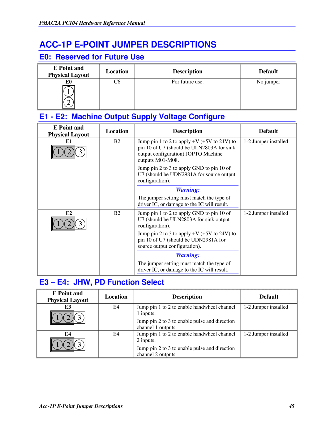
E0: Reserved for Future Use
E Point and | Location | Description | Default | |
Physical Layout | ||||
|
|
| ||
E0 | C6 | For future use. | No jumper | |
|
|
|
|
E1 - E2: Machine Output Supply Voltage Configure
E Point and | Location | Description | Default | |
Physical Layout | ||||
|
|
| ||
E1 | B2 | Jump pin 1 to 2 to apply +V (+5V to 24V) to | ||
|
| pin 10 of U7 (should be ULN2803A for sink |
| |
|
| output configuration) JOPTO Machine |
| |
|
| outputs |
| |
|
| Jump pin 2 to 3 to apply GND to pin 10 of |
| |
|
| U7 (should be UDN2981A for source output |
| |
|
| configuration). |
|
|
| Warning: |
|
|
| The jumper setting must match the type of |
|
|
| driver IC, or damage to the IC will result. |
|
|
|
|
|
E2 | B2 | Jump pin 1 to 2 to apply GND to pin 10 of | |
|
| U7 (should be ULN2803A for sink output |
|
|
| configuration). |
|
|
| Jump pin 2 to 3 to apply +V (+5V to 24V) to |
|
|
| pin 10 of U7 (should be UDN2981A for |
|
|
| source output configuration). |
|
|
|
|
|
|
| Warning: |
|
|
| The jumper setting must match the type of |
|
|
| driver IC, or damage to the IC will result. |
|
E3 – E4: JHW, PD Function Select
E Point and | Location | Description | Default | |
Physical Layout | ||||
|
|
| ||
E3 | E4 | Jump pin 1 to 2 to enable handwheel channel | ||
|
| 1 inputs. |
| |
|
| Jump pin 2 to 3 to enable pulse and direction |
| |
|
| channel 1 outputs. |
| |
E4 | E4 | Jump pin 1 to 2 to enable handwheel channel | ||
|
| 2 inputs. |
| |
|
| Jump pin 2 to 3 to enable pulse and direction |
| |
|
| channel 2 outputs. |
|
45 |