PMAC2A PC104 Hardware Reference Manual
ACC-2P E-POINT JUMPER DESCRIPTIONS
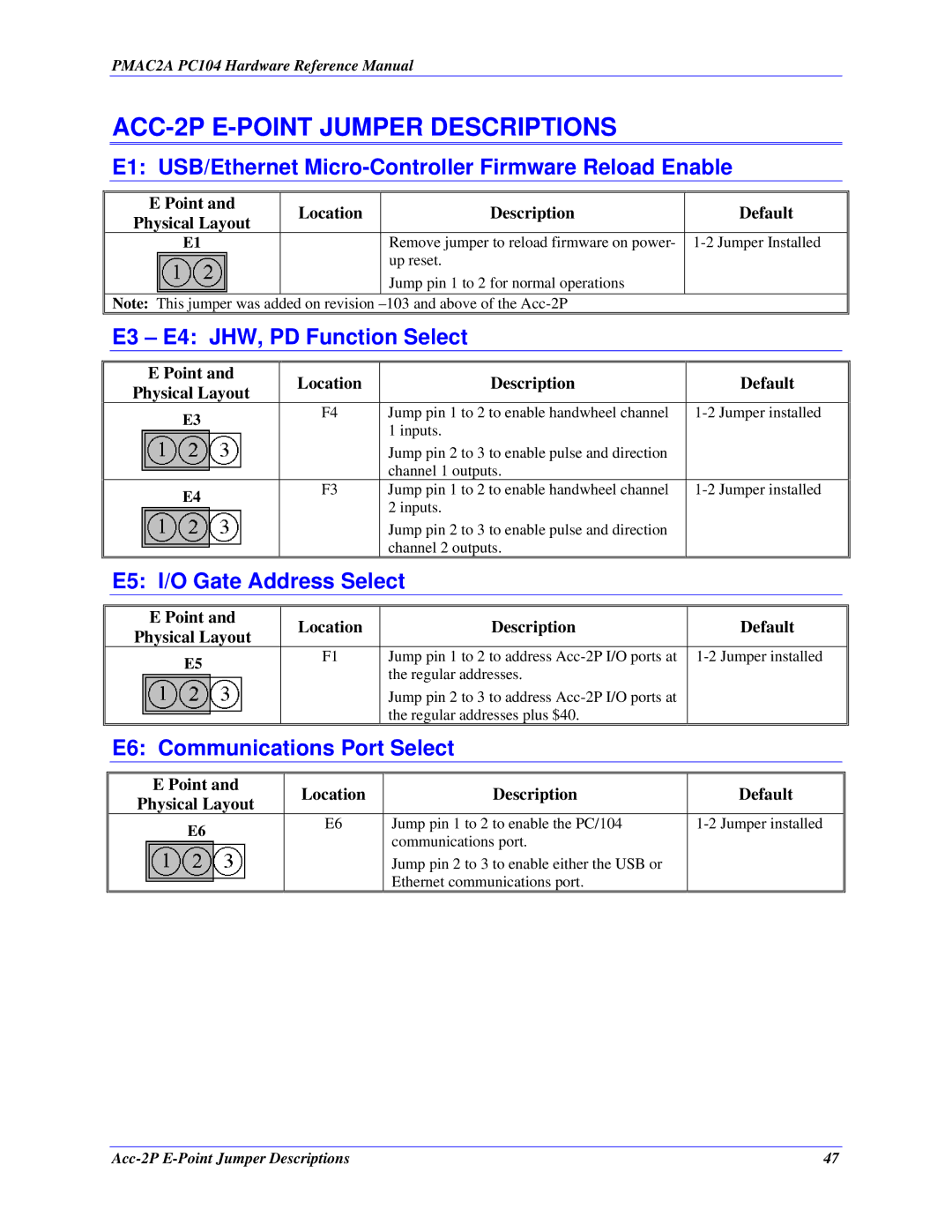
E1: USB/Ethernet Micro-Controller Firmware Reload Enable
| E Point and | Location | Description | Default |
| Physical Layout | |||
|
|
|
| |
| E1 |
| Remove jumper to reload firmware on power- | |
|
|
| up reset. |
|
|
|
| Jump pin 1 to 2 for normal operations |
|
| Note: This jumper was added on revision |
| ||
| E3 – E4: JHW, PD Function Select |
| ||
|
|
|
|
|
| E Point and | Location | Description | Default |
| Physical Layout | |||
|
|
|
| |
| E3 | F4 | Jump pin 1 to 2 to enable handwheel channel | |
|
| 1 inputs. |
| |
|
|
|
| |
|
|
| Jump pin 2 to 3 to enable pulse and direction |
|
|
|
| channel 1 outputs. |
|
| E4 | F3 | Jump pin 1 to 2 to enable handwheel channel | |
|
| 2 inputs. |
| |
|
|
|
| |
|
|
| Jump pin 2 to 3 to enable pulse and direction |
|
|
|
| channel 2 outputs. |
|
| E5: I/O Gate Address Select |
| ||
|
|
|
|
|
| E Point and | Location | Description | Default |
| Physical Layout | |||
|
|
|
| |
| E5 | F1 | Jump pin 1 to 2 to address | |
|
| the regular addresses. |
| |
|
|
|
| |
|
|
| Jump pin 2 to 3 to address |
|
|
|
| the regular addresses plus $40. |
|
| E6: Communications Port Select |
| ||
|
|
|
|
|
| E Point and | Location | Description | Default |
| Physical Layout | |||
|
|
|
| |
| E6 | E6 | Jump pin 1 to 2 to enable the PC/104 | |
|
| communications port. |
| |
|
|
|
| |
|
|
| Jump pin 2 to 3 to enable either the USB or |
|
|
|
| Ethernet communications port. |
|
47 |
