INSTALLATION
Continued
B.Clearances from the top of the firebox opening to the ceiling should not be less than 42 inches.
C.When the firebox is installed on carpeting or other combustible material, other than wood flooring, the firebox should be installed on a metal or wood panel extending the full width and depth of the enclosure.
D.Clearances from the bottom of firebox to the floor is 0 inches.
These fireboxes can be installed as freestanding units against a wall with the approved, optional cabinet mantels (see Accessories, page 35) or as a
![]() CAUTION: Do not install the firebox directly on carpet or vinyl.
CAUTION: Do not install the firebox directly on carpet or vinyl.
NOTICE: Surface temperatures ofadjacentwallsandmantelsbe- comehotduringoperation.Walls and mantels above the firebox may become hot to the touch. If installed properly, these tem- peratures meet the requirement of the national product standard. Follow all minimum clearances shown in this manual.
NOTICE: If your installation does notmeettheminimumclearances shown, you must do one of the following:
•raise the mantel to an accept- able height
•remove the mantel
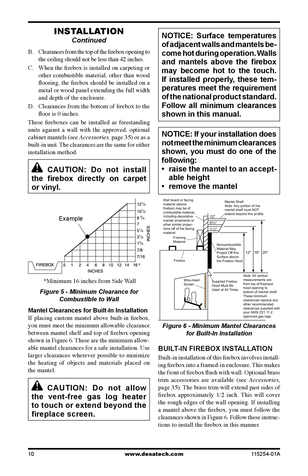
Example |
* |
*Minimum 16 inches from Side Wall
Figure 5 - Minimum Clearance for
Combustible to Wall
Mantel Clearances for
If placing custom mantel above
![]() CAUTION: Do not allow the
CAUTION: Do not allow the
Wall board or facing |
|
|
| Mantel Shelf | |||||||
material (above |
|
|
| ||||||||
|
|
| Note: Any portion of the | ||||||||
firebox) may be of |
|
|
| ||||||||
|
|
| mantel shelf must NOT | ||||||||
combustible material, |
|
|
| ||||||||
|
|
| extend beyond this profile. | ||||||||
including decorative |
| 12" |
| ||||||||
mantel ornaments or |
| 63/4" |
|
|
|
| |||||
other similar projec- |
|
|
|
|
| ||||||
tions off of the facing |
| 11/2" |
|
|
|
| |||||
|
|
|
| ||||||||
material. |
|
|
|
|
|
|
| ||||
| Framing |
|
|
|
|
|
|
| |||
| Material |
|
|
| Noncombustible |
|
|
| |||
|
|
|
|
|
|
|
|
|
|
| |
|
|
|
|
|
|
|
| Material May | 12" | 16" | 20" |
|
|
|
|
|
|
|
| Project Off this | |||
| Firebox |
|
|
| Surface above |
|
|
| |||
|
|
|
| the Firebox Hood |
|
|
| ||||
|
|
|
|
|
|
|
|
|
|
|
|
|
|
|
|
|
|
|
|
| Note: All vertical | ||
|
|
|
|
|
|
|
|
| |||
|
|
| Supplied Firebox | measurements are | |||||||
|
| Screen |
| from top of fireplace | |||||||
|
|
| Hood Must Be | ||||||||
|
|
|
|
|
| hood opening to | |||||
|
|
|
|
|
| Used at All Times | |||||
|
|
|
|
|
| bottom of mantel shelf. | |||||
|
|
|
|
|
|
|
|
| |||
|
|
|
|
|
|
|
|
| These minimum | ||
|
|
|
|
|
|
|
|
| |||
|
|
|
|
|
|
|
|
| clearances replace any | ||
|
|
|
|
|
|
|
|
| other recommended | ||
|
|
|
|
|
|
|
|
| |||
|
|
|
|
|
|
|
|
| clearances supplied with | ||
|
|
|
|
|
|
|
|
| your ANSI Z21.11.2 | ||
|
|
|
|
|
|
|
|
| approved gas logs. | ||
Figure 6 - Minimum Mantel Clearances
for
10 | www.desatech.com |