INSTALLATION
Continued
INSTALLING FIREBOX USING OPTIONAL ACCESSORY MANTELS
![]() WARNING: A qualified ser- vice person must install firebox. Follow all local codes.
WARNING: A qualified ser- vice person must install firebox. Follow all local codes.
This firebox may be installed using a cabinet mantel accessory against a wall in your home. The firebox and cabinet mantel can be installed directly on the floor. A trim kit is included with the mantel accessories.
1.Assemble cabinet mantel accessory and the trim kit. Assembly instructions are included with each accessory.
2.If using an optional blower accessory (circulat- ing models only), install a properly grounded, 120 volt
3.Install gas piping to firebox location. See Connecting to Gas Supply, page 15. You may have to cut an access hole in the floor or wall to run gas line to firebox. Make sure to locate access hole so cabinet mantel will cover it when installed (see Figure 9).
4.Place cabinet mantel on floor in desired loca- tion. Make sure mantel is flush against wall.
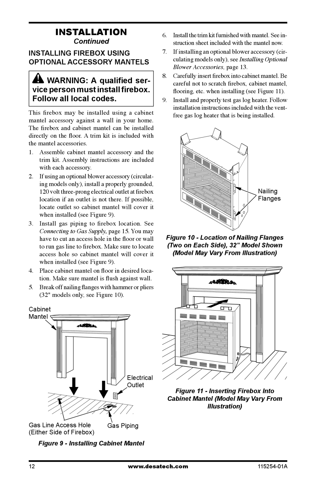
5.Break off nailing flanges with hammer or pliers (32" models only, see Figure 10).
Cabinet
Mantel ![]()
Electrical
Outlet
Gas Line Access Hole | Gas Piping |
(Either Side of Firebox) |
|
Figure 9 - Installing Cabinet Mantel
6.Install the trim kit furnished with mantel. See in- struction sheet included with the mantel now.
7.If installing an optional blower accessory (cir- culating models only), see Installing Optional Blower Accessories, page 13.
8.Carefully insert firebox into cabinet mantel. Be careful not to scratch firebox, cabinet mantel, flooring, etc. when installing (see Figure 11).
9.Install and properly test gas log heater. Follow installation instructions included with the vent- free gas log heater that is being installed.
![]()
![]()
![]()
![]()
![]()
![]()
![]() Nailing
Nailing ![]()
![]()
![]() Flanges
Flanges
Figure 10 - Location of Nailing Flanges (Two on Each Side), 32" Model Shown (Model May Vary From Illustration)
Figure 11 - Inserting Firebox Into
Cabinet Mantel (Model May Vary From
Illustration)
12 | www.desatech.com |