Fireplace

Installation

Continued

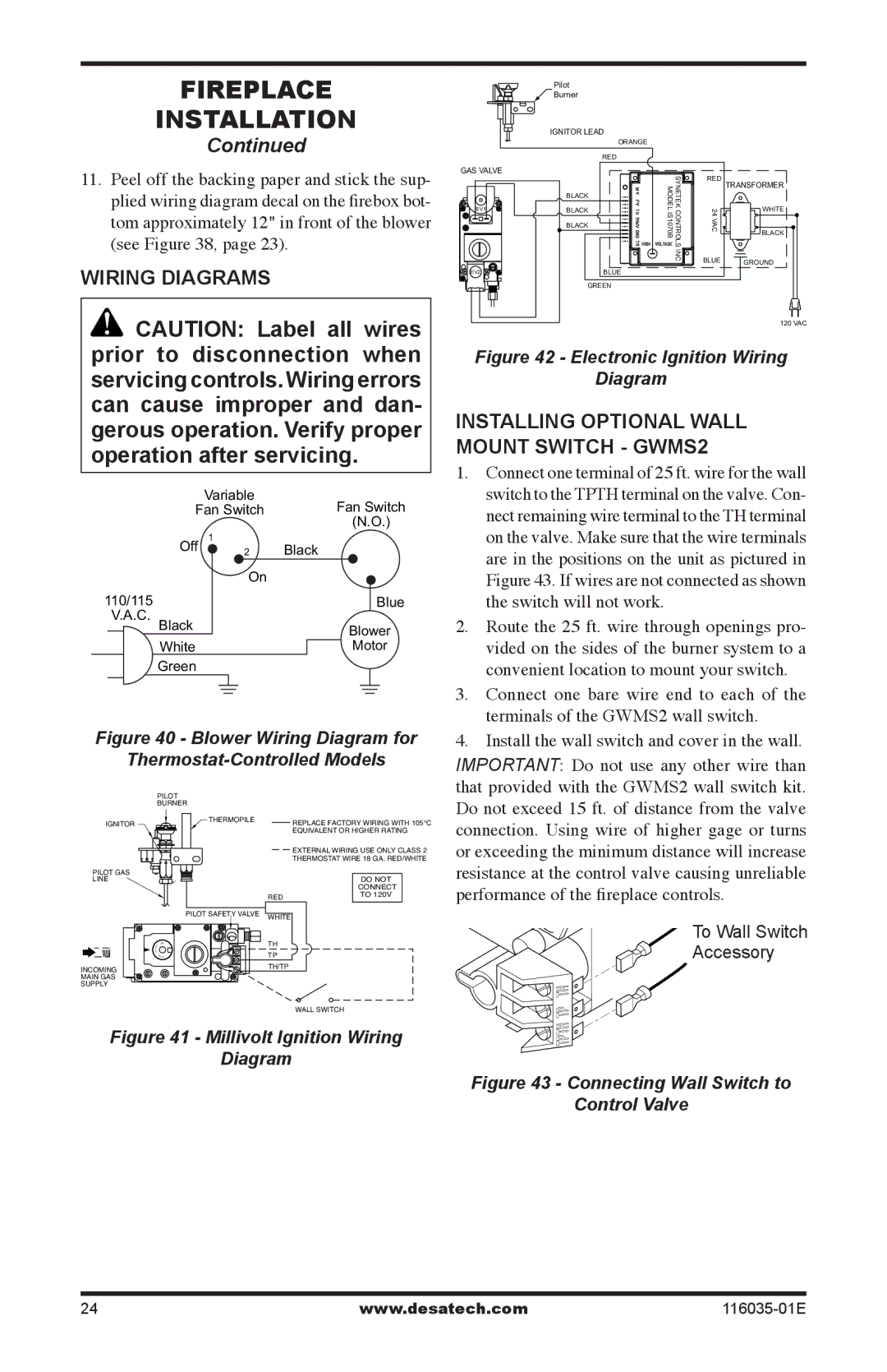
11.Peel off the backing paper and stick the sup- plied wiring diagram decal on the firebox bot- tom approximately 12" in front of the blower (see Figure 38, page 23).

Wiring Diagrams

CAUTION: Label all wires prior to disconnection when servicing controls. Wiring errors can cause improper and dan- gerous operation. Verify proper operation after servicing.


Variable

Fan Switch


Fan Switch


(N.O.)


Off

1

Black


2

110/115

On


Blue


V.A.C. Black


Blower


White


Motor

Green

Figure 40 - Blower Wiring Diagram for

Thermostat-Controlled Models

PILOT

BURNER

IGNITOR

THERMOPILE

REPLACE FACTORY WIRING WITH 105°C


EQUIVALENT OR HIGHER RATING

EXTERNAL WIRING USE ONLY CLASS 2

THERMOSTAT WIRE 18 GA. RED/WHITE

Pilot

Burner

IGNITOR LEAD

ORANGE

RED

GAS VALVE


SYNETEKCONTROLS MODELIS1070B

24VAC


RED TRANSFORMER


BLACK


EV1

BLACK


WHITE


BLACK


BLACK


INC

BLUE

GROUND


EV2


BLUE


GREEN

120 VAC

Figure 42 - Electronic Ignition Wiring

Diagram

Installing optional wall Mount Switch - gwmS2

1.

Connect one terminal of 25 ft. wire for the wall


switch to the TPTH terminal on the valve. Con-


nect remaining wire terminal to the TH terminal


on the valve. Make sure that the wire terminals


are in the positions on the unit as pictured in


Figure 43. If wires are not connected as shown


the switch will not work.

2.

Route the 25 ft. wire through openings pro-


vided on the sides of the burner system to a


convenient location to mount your switch.

3.

Connect one bare wire end to each of the


terminals of the GWMS2 wall switch.

4.

Install the wall switch and cover in the wall.

IMPORTANT: Do not use any other wire than

that provided with the GWMS2 wall switch kit.

Do not exceed 15 ft. of distance from the valve

connection. Using wire of higher gage or turns

or exceeding the minimum distance will increase

PILOT GAS

LINE

I

P

FFO

INCOMING

MAIN GAS

SUPPLY

RED

PILOT SAFETY VALVE WHITE

TH

TP

TH/TP

WALL SWITCH

DO NOT CONNECT TO 120V

resistance at the control valve causing unreliable

performance of the fireplace controls.

To Wall Switch

Accessory

Figure 41 - Millivolt Ignition Wiring

Diagram

Figure 43 - Connecting Wall Switch to

Control Valve

24

www.desatech.com

116035-01E

Page 24
Image 24
Desa (V)CD36RPE, (V)CD36TNE, (V)CD36TPE, (V)CD36RNE installation manual Wiring Diagrams

V)CD36RN, (V)CD36TN, (V)CD36RPE, (V)CD36RNE, (V)CD36RP specifications

The Desa (V)CD36TPE, (V)CD36TP, (V)CD36TNE, (V)CD36RP, and (V)CD36RNE represent a series of cutting-edge heating solutions designed to meet the diverse needs of modern users. These models stand out for their efficiency, user-friendly features, and advanced technologies that ensure optimal performance and comfort.

One of the main features of these Desa models is their impressive heating capacity. Each unit provides a reliable source of warmth, making them suitable for various environments, from residential homes to larger commercial spaces. The versatility of these models ensures that they can accommodate different room sizes and heating requirements effortlessly.

The Desa models incorporate advanced heating technologies, including efficient radiant heating systems. This technology allows for quicker heat distribution and a more comfortable ambient temperature. Users can enjoy the benefits of even heat coverage, eliminating cold spots and ensuring a pleasant living or working environment.

Energy efficiency is another critical characteristic of the Desa models. Designed with modern energy-saving features, these units help reduce energy consumption while maintaining powerful heating capabilities. This aspect not only leads to cost savings on energy bills but also contributes to a more sustainable approach to heating.

Convenience is paramount in the design of the (V)CD36 series. Many of these models come equipped with programmable thermostats and remote control options, enabling users to set their desired heating schedule with ease. This flexibility allows for personalized comfort and lets users maintain their preferred temperatures without unnecessary manual adjustments.

Safety features are also a top priority in the (V)CD36 series. Each model is equipped with essential safety mechanisms, including automatic shut-off systems and tip-over protection, ensuring peace of mind when the units are in operation.

The aesthetic design of the Desa (V)CD36 series complements various interior styles. With sleek finishes and a modern silhouette, these heating solutions blend seamlessly into any décor while providing essential functionality.

In summary, the Desa (V)CD36TPE, (V)CD36TP, (V)CD36TNE, (V)CD36RP, and (V)CD36RNE models exemplify innovation in heating technology, offering energy efficiency, safety, and user convenience. These features make them an excellent choice for anyone seeking reliable and effective heating solutions.