isENGLISH
Connect the probe to the turbine that you want to configure and witch on the instrument; the mes- sage PPL will appear on the display corresponding to input A or B.
Press the PROG key, P0 will appear on the display; using the sand tkeys, select the input to which the turbine probe connected; the previously set number of impulses per litre will appear on the display. Using the and tkeys, set the number of impulses per litre corresponding to the number of impulses per litre of the turbine that is being configured. Confirm by pressing the ENTER key; P0 appears on the display. Press ENTER: this quits the procedure for configuring a turbine with any number of impulses per litre.
CONNECTION OF PROBES TO THE PRESSURE GAUGE DATA LOGGER DO 9704
One or two pressure probes of the series TP 704 or TP 705 may be connected to the instrument, one or two temperature probes of the series TP 870, turbine probes for measuring flow rate or impulse probes for measuring flow rate.
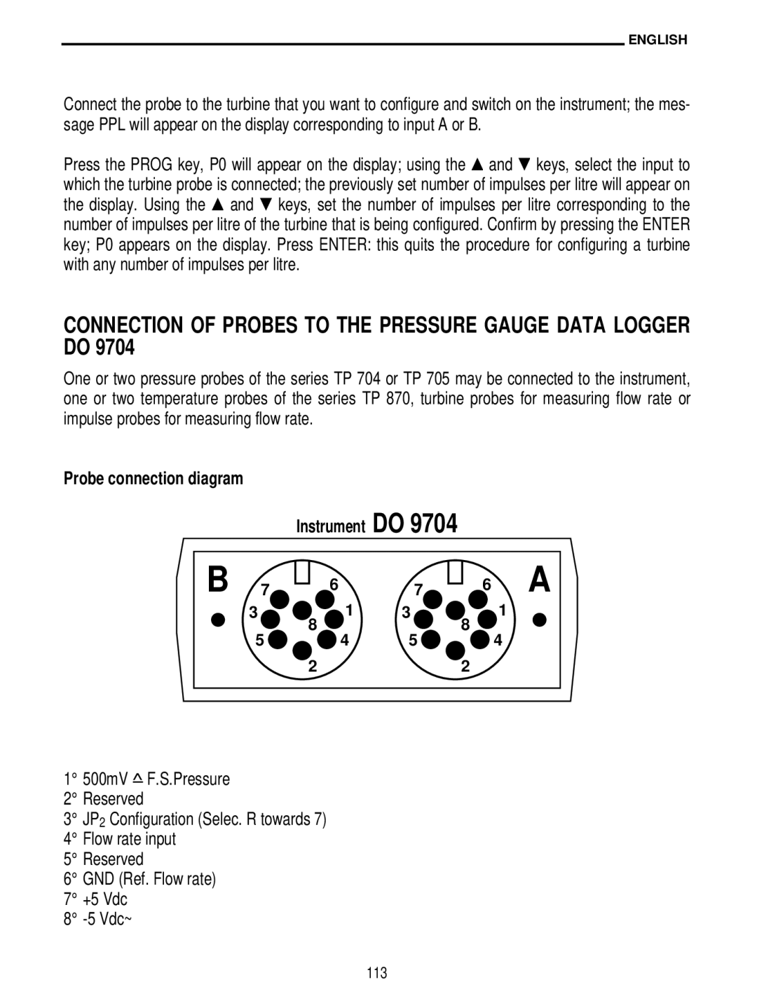
Probe connection diagram
Instrument DO 9704
B 7
3![]()
5
| 6 | 7 |
| ||
|
| |
1 | 3 | |
8 |
| |
4 | 5 | |
2 |
| |
6 A
1
8
4
2
1° 500mV ^– F.S.Pressure 2° Reserved
3° JP2 Configuration (Selec. R towards 7) 4° Flow rate input
5° Reserved
6° GND (Ref. Flow rate) 7° +5 Vdc
8°