2
Hardware Installation 


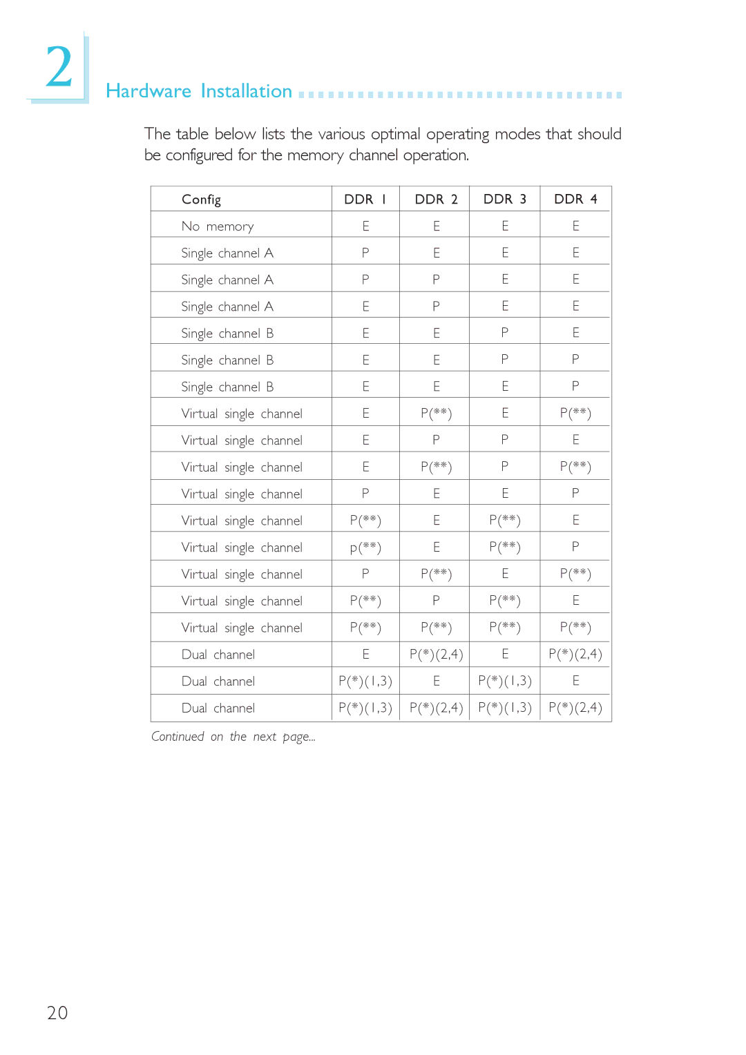
The table below lists the various optimal operating modes that should be configured for the memory channel operation.
Config |
|
| DDR 1 | DDR 2 | DDR 3 | DDR 4 | |
|
|
|
|
|
|
| |
No memory |
| E | E | E | E | ||
|
|
|
|
|
| ||
Single channel A | P | E | E | E | |||
|
|
|
|
|
| ||
Single channel A | P | P | E | E | |||
|
|
|
|
|
| ||
Single channel A | E | P | E | E | |||
|
|
|
|
|
| ||
Single channel B | E | E | P | E | |||
|
|
|
|
|
| ||
Single channel B | E | E | P | P | |||
|
|
|
|
|
| ||
Single channel B | E | E | E | P | |||
|
|
|
|
|
|
|
|
Virtual | single | channel | E | P(**) | E | P(**) | |
|
|
|
|
|
|
|
|
Virtual | single | channel | E | P | P | E | |
|
|
|
|
|
|
|
|
Virtual | single | channel | E | P(**) | P | P(**) | |
|
|
|
|
|
|
|
|
Virtual | single | channel | P | E | E | P | |
|
|
|
|
|
|
|
|
Virtual | single | channel | P(**) | E | P(**) | E | |
|
|
|
|
|
|
|
|
Virtual | single | channel | p(**) | E | P(**) | P | |
|
|
|
|
|
|
|
|
Virtual | single | channel | P | P(**) | E | P(**) | |
|
|
|
|
|
|
|
|
Virtual | single | channel | P(**) | P | P(**) | E | |
|
|
|
|
|
|
|
|
Virtual | single | channel | P(**) | P(**) | P(**) | P(**) | |
|
|
|
|
|
|
| |
Dual channel |
| E | P(*)(2,4) | E | P(*)(2,4) | ||
|
|
|
|
|
|
| |
Dual channel |
| P(*)(1,3) | E | P(*)(1,3) | E | ||
|
|
|
|
|
|
| |
Dual channel |
| P(*)(1,3) | P(*)(2,4) | P(*)(1,3) | P(*)(2,4) | ||
|
|
|
|
|
|
|
|
|
|
|
|
|
|
|
|
Continued on the next page...
20
