For Husqvarna Parts Call 606-678-9623 or 606-561-4983
CONSUMER ASSEMBLY / PRE-OPERATION
TRACTION DRIVE | RETAINER |
CONTROL LEVER | SPRING |
TRACTION
DRIVE CON-
TROL ROD
DRIVE ![]()
CONTROL
BRACKET
FIG. 4
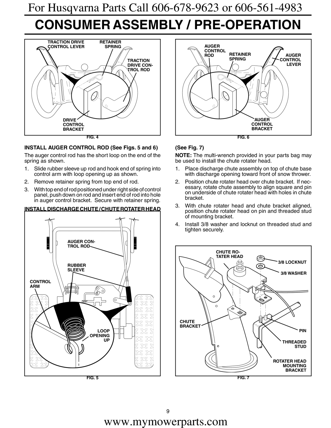
INSTALL AUGER CONTROL ROD (See Figs. 5 and 6)
The auger control rod has the short loop on the end of the spring as shown.
1.Slide rubber sleeve up rod and hook end of spring into control arm with loop opening up as shown.
2.Remove retainer spring from top end of rod.
3.With top end of rod positioned under right side of control panel, push down on rod and insert end of rod into hole in auger control bracket. Secure with retainer spring.
INSTALL DISCHARGE CHUTE / CHUTE ROTATER HEAD |
AUGER CON- |
TROL ROD |
RUBBER |
SLEEVE |
CONTROL |
ARM |
LOOP |
OPENING |
UP |
FIG. 5 |
AUGER |
|
|
CONTROL | RETAINER | AUGER |
ROD | ||
| SPRING | CONTROL |
|
| LEVER |
AUGER
CONTROL
BRACKET
FIG. 6
(See Fig. 7)
NOTE: The
1.Place discharge chute assembly on top of chute base with discharge opening toward front of snow thrower.
2.Position chute rotater head over chute bracket. If nec- essary, rotate chute assembly to align square and pin on underside of chute rotater head with holes in chute bracket.
3.With chute rotater head and chute bracket aligned, position chute rotater head on pin and threaded stud of mounting bracket.
4.Install 3/8 washer and locknut on threaded stud and tighten securely.
CHUTE RO-
TATER HEAD
![]() 3/8 LOCKNUT
3/8 LOCKNUT
3/8 WASHER
CHUTE
BRACKET
PIN
THREADED
STUD
ROTATER HEAD
MOUNTING
BRACKET
FIG. 7
9
www.mymowerparts.com