Instruction Manual

IM-106-880, Rev 1.0

January 2007

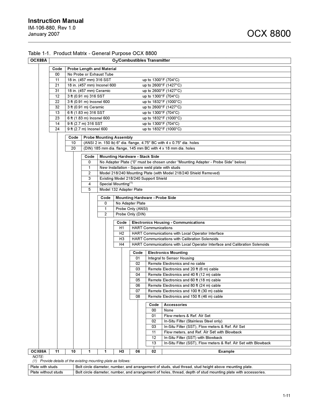
Table 1-1. Product Matrix - General Purpose OCX 8800

OCX 8800

OCX88A


O2/Combustibles Transmitter


Code

Probe Length and Material


00

No Probe or Exhaust Tube


11

18 in. (457 mm) 316 SST

up to 1300°F (704°C)


21

18 in. (457 mm) Inconel 600

up to 2600°F (1427°C)


31

18 in. (457 mm) Ceramic

up to 2600°F (1427°C)


12

3 ft (0.91 m) 316 SST

up to 1300°F (704°C)


22

3 ft (0.91 m) Inconel 600

up to 1832°F (1000°C)


32

3 ft (0.91 m) Ceramic

up to 2600°F (1427°C)


13

6 ft (1.83 m) 316 SST

up to 1300°F (704°C)


23

6 ft (1.83 m) Inconel 600

up to 1832°F (1000°C)


14

9 ft (2.7 m) 316 SST

up to 1300°F (704°C)


24

9 ft (2.7 m) Inconel 600

up to 1832°F (1000°C)


Code Probe Mounting Assembly


10(ANSI 2 in. 150 lb) 6" dia. flange, 4.75" BC with 4 x 0.75" dia. holes

20(DIN) 185 mm dia. flange, 145 mm BC with 4 x 18 mm dia. holes

Code

Mounting Hardware - Stack Side

0

No Adapter Plate (“0” must be chosen under “Mounting Adapter - Probe Side” below)

1

New Installation - Square weld plate with studs

2

Model 218/240 Mounting Plate (with Model 218/240 Shield Removed)

3

Existing Model 218/240 Support Shield

4

Special Mounting(1)

5

Model 132 Adapter Plate

Code Mounting Hardware - Probe Side

0No Adapter Plate

1Probe Only (ANSI)

2Probe Only (DIN)

Code

Electronics Housing - Communications

H1

HART Communications

H2

HART Communications with Local Operator Interface

H3

HART Communications with Calibration Solenoids

H4

HART Communications with Local Operator Interface and Calibration Solenoids

Code

Electronics Mounting

01

Integral to Sensor Housing

02

Remote Electronics and no cable

03

Remote Electronics and 20 ft (6 m) cable

04

Remote Electronics and 40 ft (12 m) cable

05

Remote Electronics and 60 ft (18 m) cable

06

Remote Electronics and 80 ft (24 m) cable

07

Remote Electronics and 100 ft (30 m) cable

08

Remote Electronics and 150 ft (46 m) cable


Code

Accessories


00

None


01

Flow meters & Ref. Air Set


02

In-Situ Filter (Stainless Steel only)


03

In-Situ Filter (SST), Flow meters & Ref. Air Set


11

Flow meters, and Ref. Air Set with Blowback


12

In-Situ Filter (SST) with Blowback


13

In-Situ Filter (SST), Flow meters & Ref. Air Set with Blowback


OCX88A

11

10

1

1

H3

06

02

Example

NOTE:

(1) Provide details of the existing mounting plate as follows:

Plate with studs

Bolt circle diameter, number, and arrangement of studs, stud thread, stud height above mounting plate.

Plate without studs

Bolt circle diameter, number, and arrangement of holes, thread, depth of stud mounting plate with accessories.

1-11

Page 19
Image 19
Emerson 8800 instruction manual IM-106-880, Rev January Product Matrix General Purpose OCX

8800 specifications

The Emerson 8800, a pivotal instrument in industrial automation, stands out for its robust features and cutting-edge technologies. Designed to enhance process efficiency and reliability, this device is integral to numerous industries, including oil and gas, chemical, and power generation.

One of the standout features of the Emerson 8800 is its advanced control capabilities. It incorporates a highly flexible control architecture that supports a wide variety of control schemes. This adaptability allows engineers to implement customized solutions tailored to specific process requirements. Additionally, the 8800 series includes integrated predictive diagnostics that continually monitor system performance, alerting operators to potential issues before they escalate into serious problems.

The technology powering the Emerson 8800 is equally impressive. Equipped with state-of-the-art microprocessors, it can handle complex calculations and data processing with remarkable speed and accuracy. The device supports multiple communication protocols, including Foundation Fieldbus, HART, and Modbus. This flexibility ensures seamless integration with existing systems, thereby enhancing data sharing and communication between devices.

Moreover, the Emerson 8800 features a user-friendly interface that simplifies operation and monitoring. The intuitive display allows operators to easily navigate through various settings and real-time data, promoting better decision-making and faster response times. This ergonomic design enhances usability in high-pressure environments, ultimately contributing to improved safety and operational efficiency.

Another key characteristic of the Emerson 8800 is its durability and reliability. Built to withstand the rigors of industrial environments, the device boasts a robust enclosure, ensuring protection against dust, moisture, and extreme temperatures. This reliability minimizes the risk of downtime, making it a cost-effective choice for industries where uptime is critical.

In summary, the Emerson 8800 emerges as a powerhouse in the realm of industrial automation. With its advanced control systems, diverse communication capabilities, user-friendly interface, and rugged design, it embodies efficiency and reliability. As industries continue to evolve, the Emerson 8800 stands ready to meet the challenges of modern automation, driving innovation and productivity in complex environments.