A |
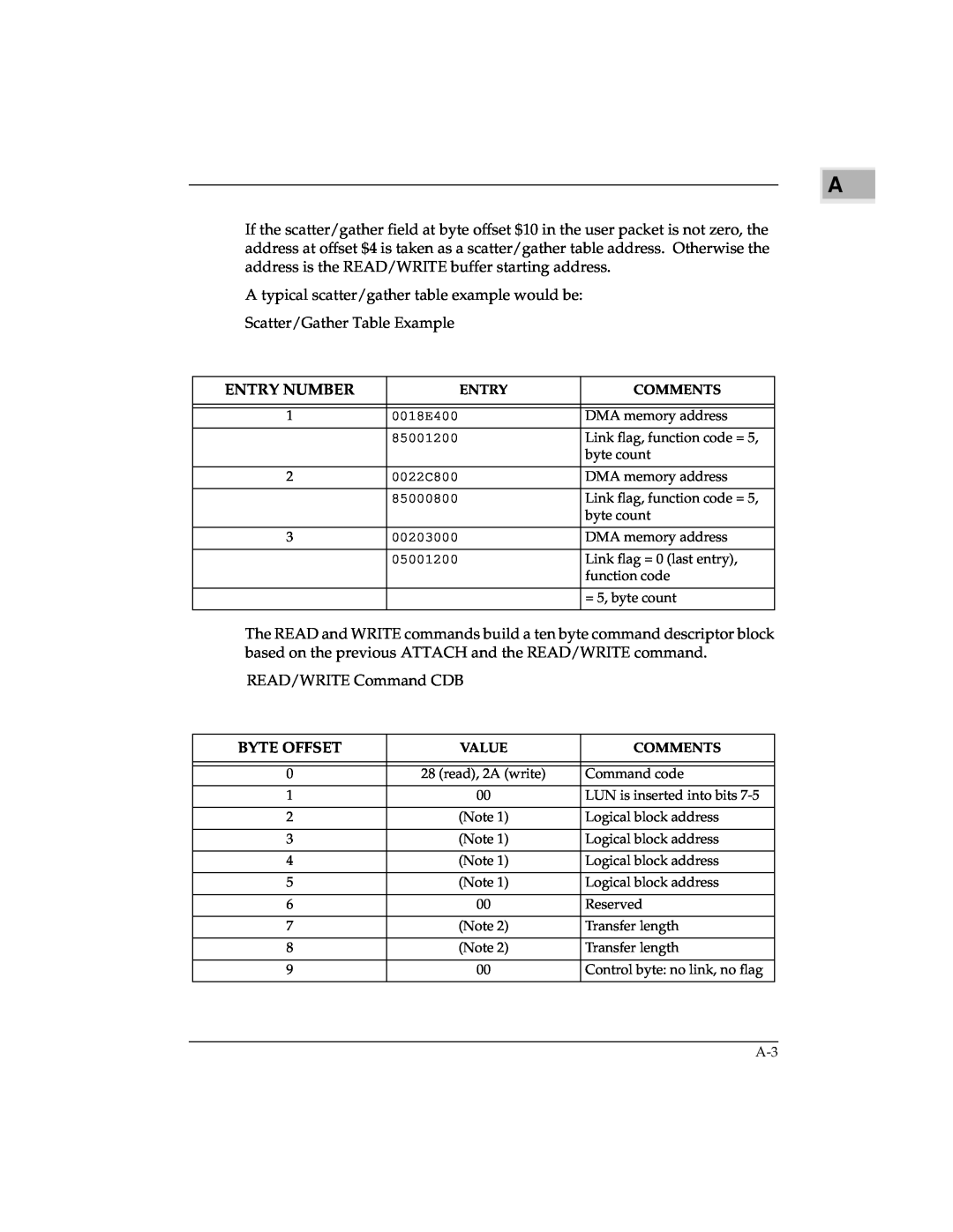
If the scatter/gather field at byte offset $10 in the user packet is not zero, the address at offset $4 is taken as a scatter/gather table address. Otherwise the address is the READ/WRITE buffer starting address.
A typical scatter/gather table example would be:
Scatter/Gather Table Example
| ENTRY NUMBER | ENTRY | COMMENTS | |
|
|
| ||
|
|
|
|
|
1 | 0018E400 | DMA memory address | ||
|
|
|
| |
|
| 85001200 | Link flag, function code = 5, | |
|
|
| byte count | |
|
|
| ||
2 | 0022C800 | DMA memory address | ||
|
|
|
| |
|
| 85000800 | Link flag, function code = 5, | |
|
|
| byte count | |
|
|
| ||
3 | 00203000 | DMA memory address | ||
|
|
|
| |
|
| 05001200 | Link flag = 0 (last entry), | |
|
|
| function code | |
|
|
|
| |
|
|
| = 5, byte count | |
|
|
|
|
|
The READ and WRITE commands build a ten byte command descriptor block based on the previous ATTACH and the READ/WRITE command.
READ/WRITE Command CDB
| BYTE OFFSET | VALUE | COMMENTS | |
|
|
| ||
|
|
|
|
|
0 | 28 (read), 2A (write) | Command code | ||
|
|
| ||
1 | 00 | LUN is inserted into bits | ||
|
|
| ||
2 | (Note 1) | Logical block address | ||
|
|
| ||
3 | (Note 1) | Logical block address | ||
|
|
| ||
4 | (Note 1) | Logical block address | ||
|
|
| ||
5 | (Note 1) | Logical block address | ||
|
|
| ||
6 | 00 | Reserved | ||
|
|
| ||
7 | (Note 2) | Transfer length | ||
|
|
| ||
8 | (Note 2) | Transfer length | ||
|
|
| ||
9 | 00 | Control byte: no link, no flag | ||
|
|
|
|
|