Servicing the TARGET Requests
STEP 3: Data Preparation
a.Decode the transfer length from the command descriptor block and load this length into the command table words $16 and $18
b.Decode the link bit and store the status to be sent to the initiator during the status phase into the STATUS word (MSB) of the command table
c.Decode the link and flag bits and store the proper message to be presented during the
d.Create a TARGET sequence custom SCSI sequence packet as described in the TARGET Sequence Custom Sequence Packet section in Chapter 2. This packet should contain a pointer to the script described above and to the command table that was created or used. (You may wish to use the same command table that was provided for the TARGET enable call to the SCSI firmware.)
STEP 4: Call the SCSI Firmware
Point address register A2 to the packet created in Step 3d. above and jump into the SCSI firmware through the FUNNEL command entry.
Example: Servicing the RECEIVE command through the TARGET sequence firmware packet.
STEP 1: Command Interpretation
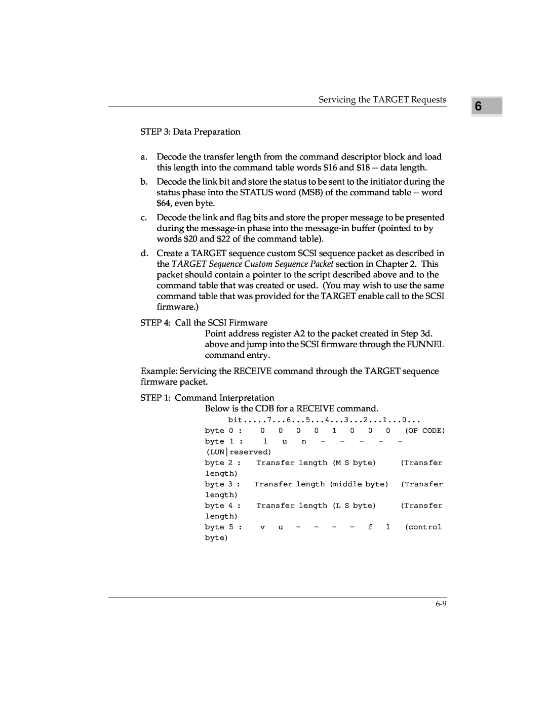
Below is the CDB for a RECEIVE command.
bit.....7...6...5...4...3...2...1...0...
byte 0 : | 0 | 0 | 0 | 0 | 1 | 0 | 0 | 0 | (OP CODE) |
byte 1 : | l | u | n | - |
| - | - | - | - |
(LUNreserved) |
|
|
|
|
|
|
|
| |
byte 2 : | Transfer length (M S byte) |
| (Transfer | ||||||
length) |
|
|
|
|
|
|
|
|
|
byte 3 : Transfer length (middle byte) | (Transfer | ||||||||
length) |
|
|
|
|
|
|
|
|
|
byte 4 : | Transfer length (L S byte) |
| (Transfer | ||||||
length) |
|
|
|
|
|
|
|
|
|
byte 5 : | v | u | - | - | - | - | f | l | (control |
byte) |
|
|
|
|
|
|
|
|
|
6 |