|
|
| Installation and |
|
Table 4 - DC cable wire size |
|
|
| |
|
|
|
|
|
| 1 RECT. POSITION | 2 RECT. POSITIONS | 3 RECT. POSITIONS |
|
| 8 AWG | 6 AWG | 4 AWG |
|
|
|
|
|
|
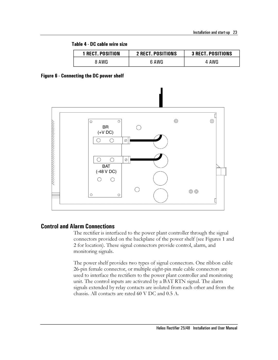
Figure 6 - Connecting the DC power shelf
Control and Alarm Connections
The rectifier is interfaced to the power plant controller through the signal connectors provided on the backplane of the power shelf (see Figures 1 and 2 for location). These signal connectors provide control, alarm, and monitoring signals.
The power shelf provides two types of signal connectors. One ribbon cable
Helios Rectifier 25/48 Installation and User Manual
