22 Installation and
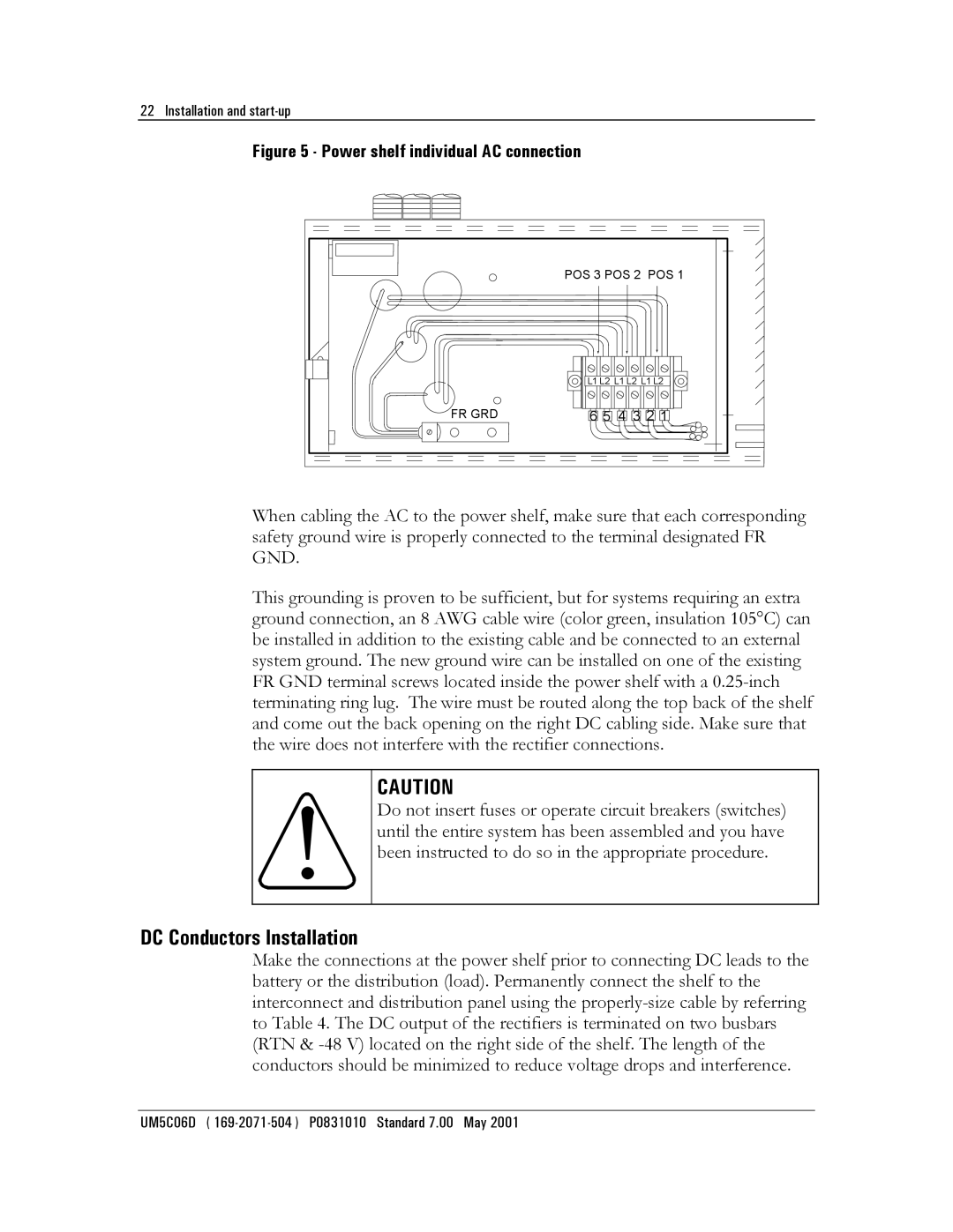
Figure 5 - Power shelf individual AC connection
| POS 3 POS 2 POS 1 |
| L1 L2 L1 L2 L1 L2 |
FR GRD | 6 5 4 3 2 1 |
When cabling the AC to the power shelf, make sure that each corresponding safety ground wire is properly connected to the terminal designated FR GND.
This grounding is proven to be sufficient, but for systems requiring an extra ground connection, an 8 AWG cable wire (color green, insulation 105°C) can be installed in addition to the existing cable and be connected to an external system ground. The new ground wire can be installed on one of the existing FR GND terminal screws located inside the power shelf with a
CAUTION
Do not insert fuses or operate circuit breakers (switches) until the entire system has been assembled and you have been instructed to do so in the appropriate procedure.
DC Conductors Installation
Make the connections at the power shelf prior to connecting DC leads to the battery or the distribution (load). Permanently connect the shelf to the interconnect and distribution panel using the
UM5C06D (