A794 Owner’s Guide | Chapter 5: Communication Interface |
Parallel Interface
The printer is also available with an
IEEE Bi-directional Parallel Connector
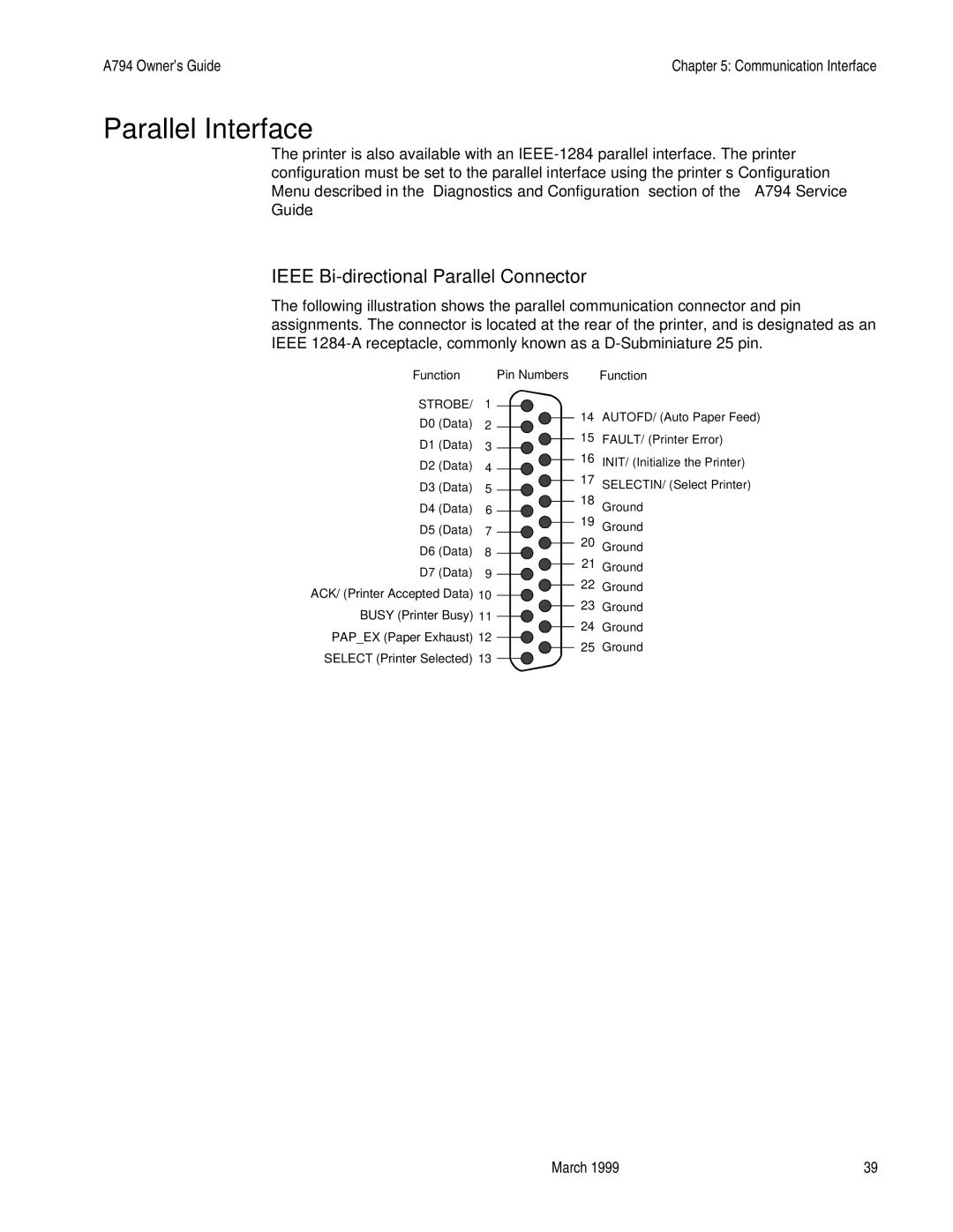
The following illustration shows the parallel communication connector and pin assignments. The connector is located at the rear of the printer, and is designated as an IEEE
Function |
| Pin Numbers | Function | |||||||
STROBE/ | 1 |
|
|
|
|
|
| 14 | AUTOFD/ (Auto Paper Feed) | |
|
|
|
|
|
| |||||
D0 (Data) | 2 |
|
|
|
|
|
| |||
|
|
|
|
|
| 15 | FAULT/ (Printer Error) | |||
D1 (Data) | 3 |
|
|
|
| |||||
|
|
|
|
|
| 16 | INIT/ (Initialize the Printer) | |||
D2 (Data) | 4 |
|
|
|
|
| ||||
|
|
|
|
|
| 17 |
| |||
D3 (Data) | 5 |
|
|
|
|
| SELECTIN/ (Select Printer) | |||
|
|
|
| |||||||
D4 (Data) | 6 |
|
|
|
|
|
| 18 | Ground | |
|
|
|
|
|
|
| 19 | |||
D5 (Data) | 7 |
|
|
|
|
| Ground | |||
|
|
|
|
| ||||||
D6 (Data) | 8 |
|
|
|
|
| 20 | Ground | ||
|
|
|
|
|
| 21 |
| |||
D7 (Data) | 9 |
|
|
|
|
| Ground | |||
|
|
|
|
|
| 22 | Ground | |||
ACK/ (Printer Accepted Data) 10 |
|
|
|
|
| |||||
|
|
|
|
|
|
| 23 | Ground | ||
BUSY (Printer Busy) 11 |
|
|
|
|
| |||||
|
|
|
|
|
|
| 24 | Ground | ||
PAP_EX (Paper Exhaust) 12 |
|
|
|
|
| |||||
|
|
|
|
|
|
| 25 | Ground | ||
SELECT (Printer Selected) 13 |
|
|
|
|
|
| ||||
|
|
|
|
|
|
|
|
| ||
March 1999 | 39 |
