Extron electronic 3200 Series, 6400 Series manual Matrix 3200 & 6400 Video Switcher System Overview

Models: 3200 Series 6400 Series

1 72
Download 72 pages 38.53 Kb
Page 10
Image 10

Chapter 1 • Introduction to the Matrix 3200/6400 Video Switcher

Matrix 3200 & 6400 Video Switcher System Overview

A Matrix 3200/6400 Video Switcher System may consist of 1 to 3 Matrix 3200 and/or Matrix 6400 Video BMEs (Basic Module Enclosures). Three video formats are supported, composite video, S-Video and component video. The switcher system may be dedicated to any one video format or a combination of all three formats in almost any configuration. What makes this possible is the switcher’s unique ability to accept virtual connector assignments of its physical connectors. Virtual assignments are done through the RS-232 serial port of the switcher from a Host computer using Extron supplied software. If a system consists of more than one switcher, the Host computer communicates with the switcher designated as BME #0 which communicates with the other switcher(s). When Virtual assignments have been completed, the system is considered to be Virtualized.

One or more physical input connectors may be assigned as any Virtual input number, the same is true of the output connectors. Virtual input and output assignments are done through BME #0’s RS-232/RS-422 communications port with a PC computer using Extron’s Matrix 3200/6400 System Virtualization/ Control software. This will probably need to be done during initial system installation (before installing input and output cables) and would not normally need to be repeated unless the system configuration changed. After the Virtual inputs and outputs have been assigned (the system has been Virtualized), the input and output cables are installed. Input/output selection (Ties and/or Presets) may be done through the RS-232/RS-422 port with a PC Host or from a touch screen or any other user-supplied controlling device, such as AMX, Creston, etc., that is capable of generating the proper commands, or, with an optional FPC 1000 Front Panel Controller.

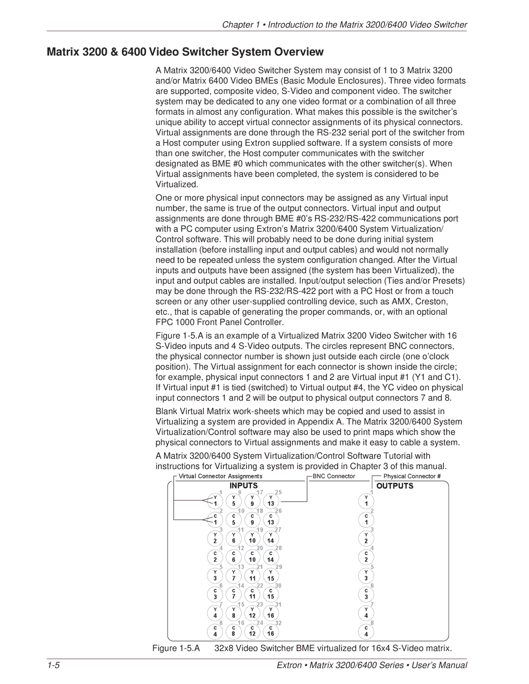
Figure 1-5.A is an example of a Virtualized Matrix 3200 Video Switcher with 16 S-Video inputs and 4 S-Video outputs. The circles represent BNC connectors, the physical connector number is shown just outside each circle (one o’clock position). The Virtual assignment for each connector is shown inside the circle; for example, physical input connectors 1 and 2 are Virtual input #1 (Y1 and C1). If Virtual input #1 is tied (switched) to Virtual output #4, the YC video on physical input connectors 1 and 2 will be output to physical output connectors 7 and 8.

Blank Virtual Matrix work-sheets which may be copied and used to assist in Virtualizing a system are provided in Appendix A. The Matrix 3200/6400 System Virtualization/Control software may also be used to print maps which show the physical connectors to Virtual assignments and make it easy to cable a system.

A Matrix 3200/6400 System Virtualization/Control Software Tutorial with instructions for Virtualizing a system is provided in Chapter 3 of this manual.

Figure 1-5.A 32x8 Video Switcher BME virtualized for 16x4 S-Video matrix.

1-5

Extron • Matrix 3200/6400 Series • User’s Manual

Page 10
Image 10
Extron electronic 3200 Series, 6400 Series manual Matrix 3200 & 6400 Video Switcher System Overview