Chapter 3 • Tutorial - Using the Matrix 3200/6400 System Virtualization/Control Software
•If you wish to group certain virtual outputs together so that you may later create Room Presets, now would be a good time to Create ROOMS by clicking
CONFIGUREROOM CONFIGURATION.
•You can create a
•From the Virtual Map screen menu, click RETURN TO MAIN and note that the number of input and output boxes shown on the Main screen matches the number of virtual input and virtual outputs created by the virtualization. The virtualization of the system is now complete and the map has been stored in BME #0. Unless the map gets destroyed or needs to be regenerated because of a system hardware reconfiguration (size, type, or number of BMEs changes) or you wish to change the virtual configuration, there is no requirement to use the Windows Virtualization/Control software. You can, however, continue to use it to control and program (set Ties, Presets, etc.) the system at any time.
How to Create ROOMS within the Matrix 3200/6400 System
The following steps use the Windows Virtualization/Control Program to optionally define Rooms in the Matrix 3200/6400 system. A Room is a group of virtual outputs that are logically associated with each other, probably by location (such as 3 video monitors and a VCR all located at a building’s security desk). A Room consists of from 1 to 16 virtual outputs and the Matrix 3200/6400 supports up to 10 Rooms. Each Room can have a name (for user friendliness, up to 12 characters long) and up to 10 Presets assigned to it (for a total of 100 Room Presets). Unlike the 32 Global Presets, Room Presets only affect those virtual outputs associated with that Room and do not change any other connections in the Matrix, making the use of Presets much more simple and flexible. Room Presets are particularly useful in conjunction with the
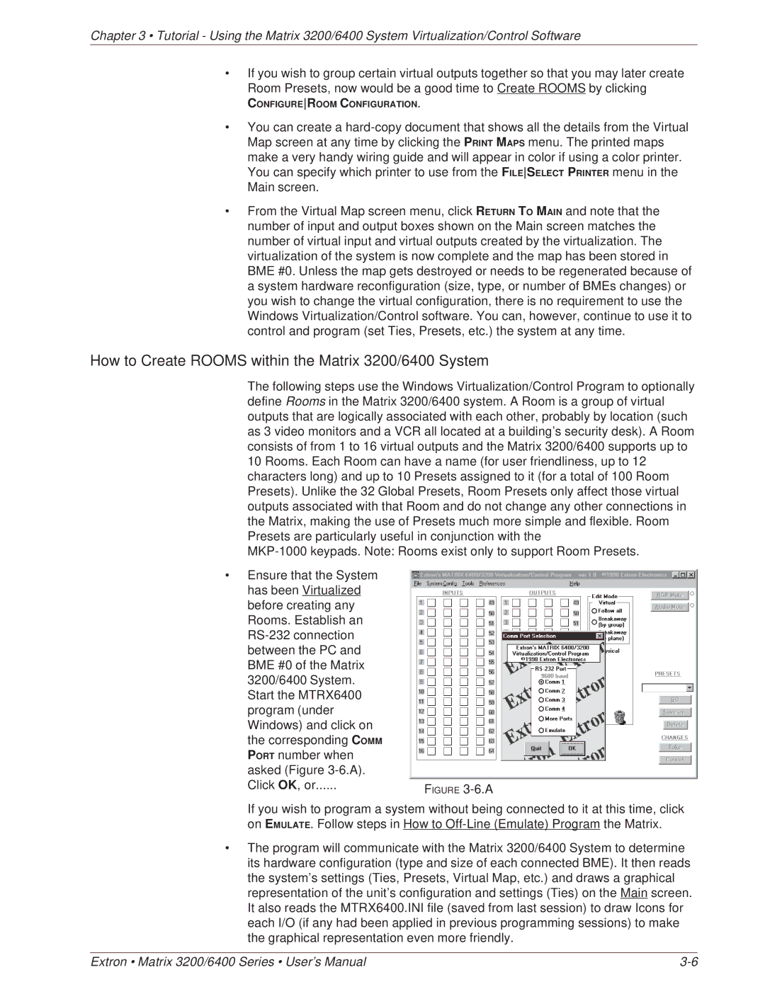
•Ensure that the System has been Virtualized before creating any Rooms. Establish an
Click OK, or | FIGURE |
|
If you wish to program a system without being connected to it at this time, click on EMULATE. Follow steps in How to
•The program will communicate with the Matrix 3200/6400 System to determine its hardware configuration (type and size of each connected BME). It then reads the system’s settings (Ties, Presets, Virtual Map, etc.) and draws a graphical representation of the unit’s configuration and settings (Ties) on the Main screen. It also reads the MTRX6400.INI file (saved from last session) to draw Icons for each I/O (if any had been applied in previous programming sessions) to make the graphical representation even more friendly.
Extron • Matrix 3200/6400 Series • User’s Manual |