Chapter 4 • Programmer’s Guide
ADVANCED INSTRUCTION SET AND SIMPLE INSTRUCTION SET COMMANDS (PAGE 1 OF 3)
VIEW COMMANDS | ASCII | RESPONSE |
|
|
| |||||||||||||
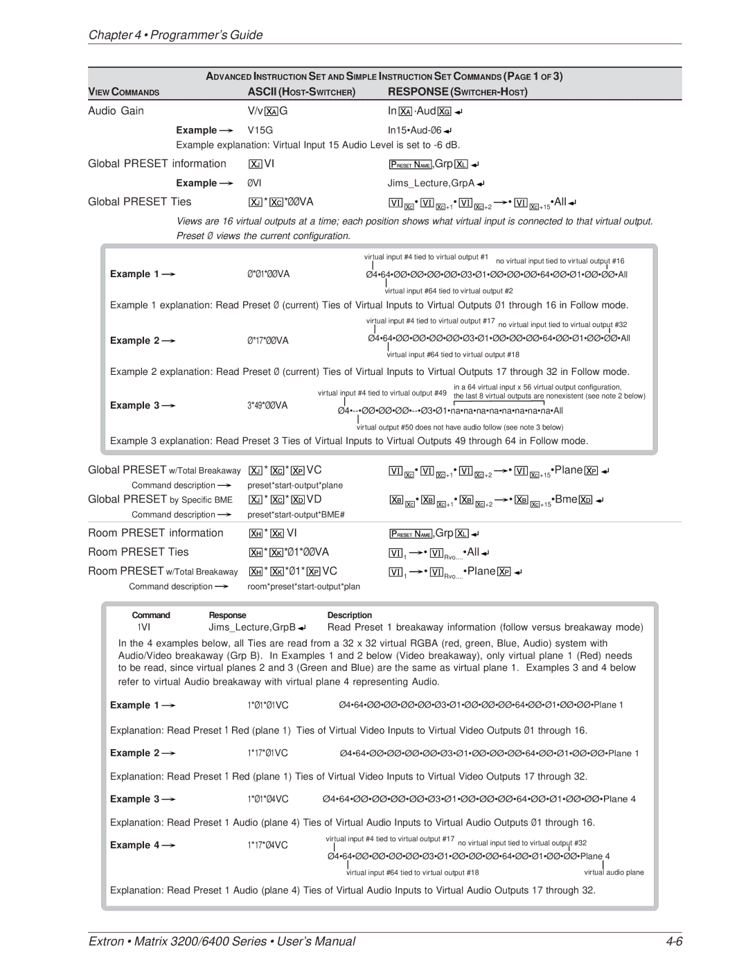
Audio Gain | V/v | G | In ·Aud |
|
|
|
|
|
|
|
|
|
|
|
| |||
|
|
|
|
|
|
|
|
|
|
|
| |||||||
|
|
|
|
|
|
|
|
|
|
|
| |||||||
Example |
| V15G |
|
|
|
|
|
|
|
|
|
|
|
|
| |||
|
|
|
|
|
|
|
|
|
|
|
|
|
| |||||
Example explanation: Virtual Input 15 Audio Level is set to |
|
|
|
|
|
|
|
| ||||||||||
Global PRESET information | VI |
|
|
| ,Grp |
|
|
|
|
|
|
|
| |||||
|
|
|
|
|
|
|
|
|
|
| ||||||||
|
|
|
|
|
|
|
|
|
|
| ||||||||
Example |
| ØVI |
| Jims_Lecture,GrpA |
|
|
|
|
|
|
|
| ||||||
|
|
|
|
|
|
|
|
|
| |||||||||
Global PRESET Ties | * | *ØØ VA |
| • | +1• |
|
| +2 |
| • | +15•All |
|
| |||||
|
|
|
|
| ||||||||||||||
|
|
|
|
| ||||||||||||||
Views are 16 virtual outputs at a time; each position shows what virtual input is connected to that virtual output. Preset Ø views the current configuration.
|
|
| virtual input #4 tied to virtual output #1 | no virtual input tied to virtual output #16 |
| ||
Example 1 |
| Ø*Ø1*ØØ VA |
|
|
| ↵ | |
|
| Ø4•64•ØØ•ØØ•ØØ•ØØ•Ø3•Ø1•ØØ•ØØ•ØØ•64•ØØ•Ø1•ØØ•ØØ•All | |||||
| |||||||
virtual input #64 tied to virtual output #2
Example 1 explanation: Read Preset Ø (current) Ties of Virtual Inputs to Virtual Outputs Ø1 through 16 in Follow mode.
|
|
| virtual input #4 tied to virtual output #17 no virtual input tied to virtual output #32 | ↵ | |||
|
|
|
|
|
|
| |
Example 2 |
| Ø*17*ØØ VA |
|
| Ø4•64•ØØ•ØØ•ØØ•ØØ•Ø3•Ø1•ØØ•ØØ•ØØ•64•ØØ•Ø1•ØØ•ØØ•All | ||
|
|
| |||||
|
|
|
|
|
|
|
|
virtual input #64 tied to virtual output #18
Example 2 explanation: Read Preset Ø (current) Ties of Virtual Inputs to Virtual Outputs 17 through 32 in Follow mode.
in a 64 virtual input x 56 virtual output configuration,
Example 3 |
| 3*49*ØØ VA | virtual input #4 tied to virtual output #49 the last 8 virtual outputs are nonexistent (see note 2 below) | |
| ↵ | |||
|
|
| ||
virtual output #50 does not have audio follow (see note 3 below)
Example 3 explanation: Read Preset 3 Ties of Virtual Inputs to Virtual Outputs 49 through 64 in Follow mode.
Global PRESET w/Total Breakaway | * | * | VC | • | +1• | +2 |
|
| • | ||
| |||||||||||
Command description |
|
|
|
|
|
|
|
| |||
|
|
|
|
|
|
| |||||
Global PRESET by Specific BME | * | * | VD | • | +1• | +2 |
|
| • | ||
|
| ||||||||||
+15•Plane ![]()
![]()
![]()
+15•Bme ![]()
![]()
![]()
Command description |
|
|
|
|
|
|
|
|
|
|
|
| ||
|
|
|
|
|
|
|
|
|
|
| ||||
Room PRESET information | * | VI |
|
|
| ,Grp |
|
|
|
|
|
| ||
|
|
|
| |||||||||||
|
|
|
| |||||||||||
Room PRESET Ties | * | *Ø1*ØØ VA | 1 |
| • | Rvo....•All |
|
|
|
| ||||
|
| |||||||||||||
|
| |||||||||||||
Room PRESET w/Total Breakaway | * | *Ø1* VC | 1 |
| • | Rvo....•Plane |
|
| ||||||
|
| |||||||||||||
|
| |||||||||||||
Command description |
|
| ||||
| ||||||
Command | Response |
|
| Description | ||
1VI | Jims_Lecture,GrpB |
| Read Preset 1 breakaway information (follow versus breakaway mode) | |||
| ||||||
| ||||||
In the 4 examples below, all Ties are read from a 32 x 32 virtual RGBA (red, green, Blue, Audio) system with Audio/Video breakaway (Grp B). In Examples 1 and 2 below (Video breakaway), only virtual plane 1 (Red) needs to be read, since virtual planes 2 and 3 (Green and Blue) are the same as virtual plane 1. Examples 3 and 4 below
refer to virtual Audio breakaway with virtual plane 4 representing Audio.
Example 1 |
| 1*Ø1*Ø1VC | Ø4•64•ØØ•ØØ•ØØ•ØØ•Ø3•Ø1•ØØ•ØØ•ØØ•64•ØØ•Ø1•ØØ•ØØ•Plane 1 | ↵ |
|
Explanation: Read Preset 1 Red (plane 1) Ties of Virtual Video Inputs to Virtual Video Outputs Ø1 through 16.
Example 2 |
| 1*17*Ø1VC | Ø4•64•ØØ•ØØ•ØØ•ØØ•Ø3•Ø1•ØØ•ØØ•ØØ•64•ØØ•Ø1•ØØ•ØØ•Plane 1 | ↵ |
|
Explanation: Read Preset 1 Red (plane 1) Ties of Virtual Video Inputs to Virtual Video Outputs 17 through 32.
Example 3 |
| 1*Ø1*Ø4VC | Ø4•64•ØØ•ØØ•ØØ•ØØ•Ø3•Ø1•ØØ•ØØ•ØØ•64•ØØ•Ø1•ØØ•ØØ•Plane 4 | ↵ |
|
Explanation: Read Preset 1 Audio (plane 4) Ties of Virtual Audio Inputs to Virtual Audio Outputs Ø1 through 16.
Example 4 |
| 1*17*Ø4VC | virtual input #4 tied to virtual output #17 no virtual input tied to virtual output |
| #32 |
| ↵ | ||||
|
| ||||||||||
|
|
| Ø4•64•ØØ•ØØ•ØØ•ØØ•Ø3•Ø1•ØØ•ØØ•ØØ•64•ØØ•Ø1•ØØ•ØØ•Plane 4 |
|
| ||||||
|
|
|
|
|
| virtual input #64 tied to virtual output #18 | virtual |
| audio plane | ||
|
|
|
|
|
| ||||||
Explanation: Read Preset 1 Audio (plane 4) Ties of Virtual Audio Inputs to Virtual Audio Outputs 17 through 32.
Extron • Matrix 3200/6400 Series • User’s Manual |