Chapter 3 • Tutorial - Using the Matrix 3200/6400 System Virtualization/Control Software
•The program will communicate with the Matrix 3200/6400 System to determine its hardware configuration (type and size of each connected BME). It then reads the system’s settings (Ties, Presets, Virtual Map, etc.) and draws a graphical representation of the unit’s configuration and settings (Ties) on the Main screen (Figure
NOTE: If this is a new system that has not been virtualized yet or one that has had its map cleared, the graphical representation and all information shown on the Virtual Map screen may be invalid at this time.
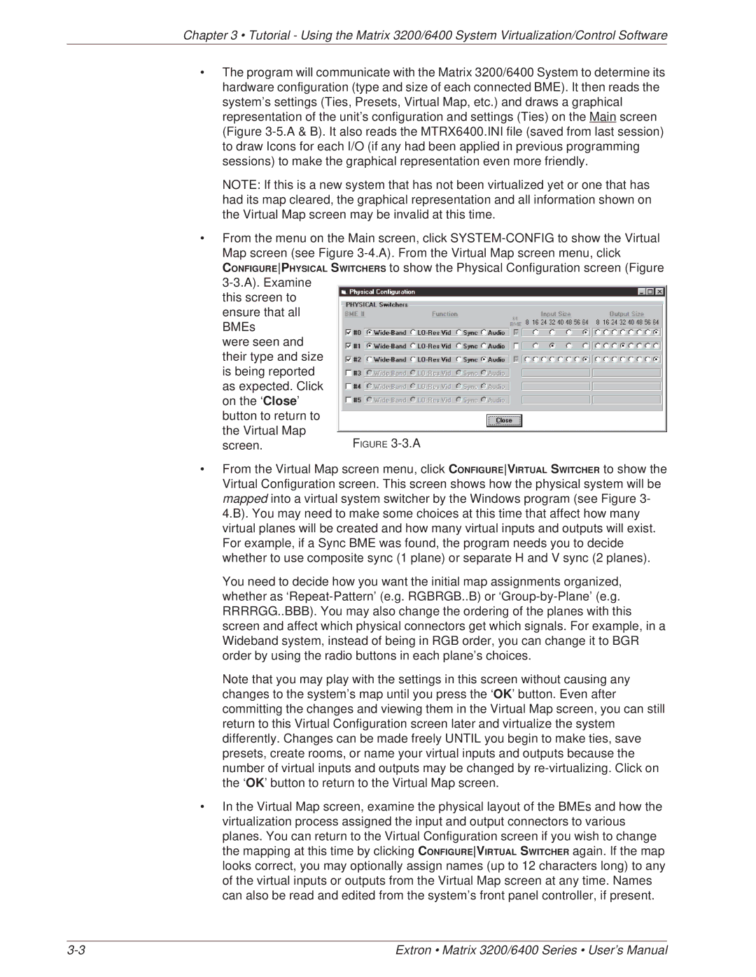
•From the menu on the Main screen, click
this screen to ensure that all BMEs
were seen and their type and size is being reported as expected. Click on the ‘Close’ button to return to the Virtual Map
screen.
•From the Virtual Map screen menu, click CONFIGUREVIRTUAL SWITCHER to show the Virtual Configuration screen. This screen shows how the physical system will be mapped into a virtual system switcher by the Windows program (see Figure 3- 4.B). You may need to make some choices at this time that affect how many virtual planes will be created and how many virtual inputs and outputs will exist. For example, if a Sync BME was found, the program needs you to decide whether to use composite sync (1 plane) or separate H and V sync (2 planes).
You need to decide how you want the initial map assignments organized, whether as
Note that you may play with the settings in this screen without causing any changes to the system’s map until you press the ‘OK’ button. Even after committing the changes and viewing them in the Virtual Map screen, you can still return to this Virtual Configuration screen later and virtualize the system differently. Changes can be made freely UNTIL you begin to make ties, save presets, create rooms, or name your virtual inputs and outputs because the number of virtual inputs and outputs may be changed by
•In the Virtual Map screen, examine the physical layout of the BMEs and how the virtualization process assigned the input and output connectors to various planes. You can return to the Virtual Configuration screen if you wish to change the mapping at this time by clicking CONFIGUREVIRTUAL SWITCHER again. If the map looks correct, you may optionally assign names (up to 12 characters long) to any of the virtual inputs or outputs from the Virtual Map screen at any time. Names can also be read and edited from the system’s front panel controller, if present.
Extron • Matrix 3200/6400 Series • User’s Manual |