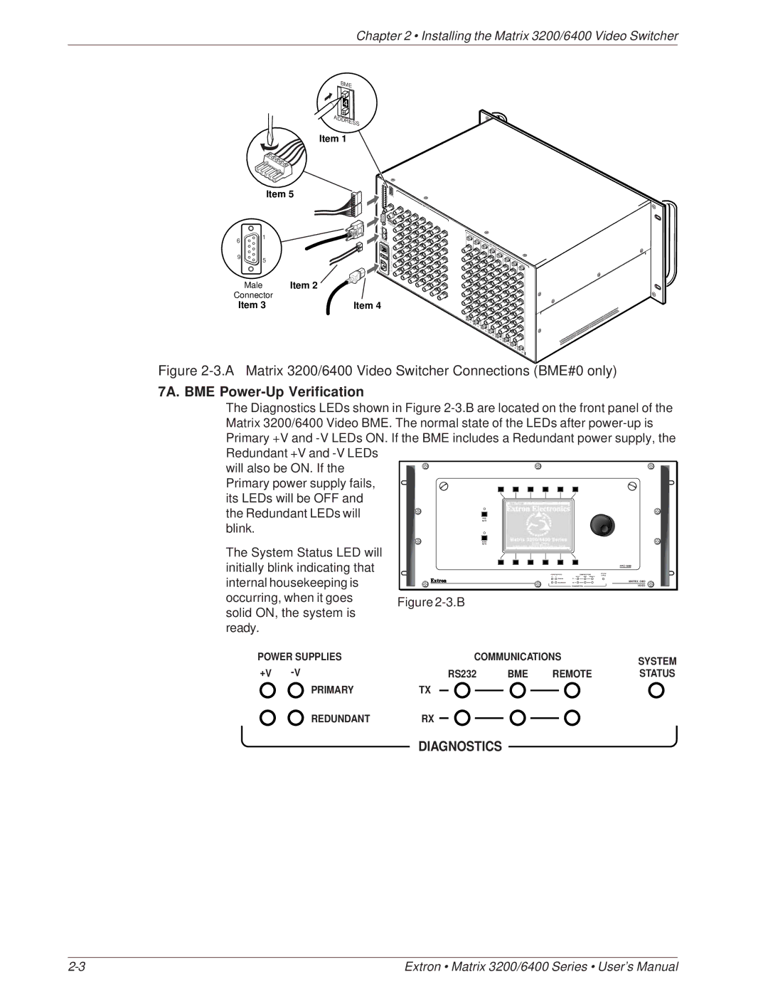
The Diagnostics LEDs shown in Figure 2-3.B are located on the front panel of the Matrix 3200/6400 Video BME. The normal state of the LEDs after power-up is Primary +V and -V LEDs ON. If the BME includes a Redundant power supply, the Redundant +V and -V LEDs
will also be ON. If the Primary power supply fails,
its LEDs will be OFF and
the Redundant LEDs will
RGB
MUTE
blink.
AUDIO
MUTE
Chapter 2 • Installing the Matrix 3200/6400 Video Switcher
BME 4
ADDRESS
Item 1
Item 5
A B C D E A B C D E
| BME |
| 4 |
MKP COMM. | ADDRESS |
|
INPUTS
|
|
| AN |
|
|
| MAAHEI |
|
|
| DEINM,CA |
|
| IN | USA |
| 1 | BMECOMM. | |
| FACPO | ||
|
| OUT |
|
6 |
| USE: | WER |
|
| 250V 5INPUT | |
|
|
| .0ATT |
9 | 5 |
| 50/60Hz |
| MAX | ||
|
| 0.5A | |
|
|
| |
| Male | Item 2 |
|
Connector |
|
| |
Item 3 | Item 4 |
IN![]()
IN![]()
1 | |
|
OUTPUTS
![]()
![]()
![]()
![]()
![]()
![]() 0
0
Figure 2-3.A Matrix 3200/6400 Video Switcher Connections (BME#0 only)
7A. BME Power-Up Verification
The System Status LED will initially blink indicating that internal housekeeping is occurring, when it goes solid ON, the system is ready.
POWER SUPPLIES
+V
PRIMARY
REDUNDANT
|
| |
POWER SUPPLIES | COMMUNICATIONS | SYSTEM |
STATUS | ||
+V | RS232 BME REMOTE |
|
PRIMARY | TX |
|
REDUNDANT | RX | MATRIX 6400 |
| DIAGNOSTICS | VIDEO |
Figure 2-3.B
COMMUNICATIONS | SYSTEM | ||
|
|
| |
RS232 | BME | REMOTE | STATUS |
TX
RX
DIAGNOSTICS
Extron • Matrix 3200/6400 Series • User’s Manual |