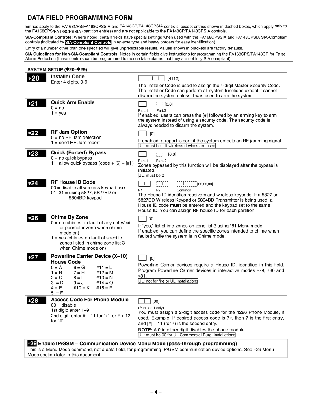
FA148CPSSIA specifications
First Alert FA148CPSSIA is a premium smoke and carbon monoxide detector that stands out for its advanced features and technologies, designed to enhance home safety. This innovative device provides dual protection against two of the most dangerous threats faced in homes: smoke from potential fires and carbon monoxide, a silent killer that is odorless and colorless.One of the main features of the FA148CPSSIA is its voice alert system. This device does not just sound an alarm; it provides an intelligible voice alert that appraises homeowners on the specific type of danger. This feature allows users to quickly identify whether they are facing a smoke or carbon monoxide event, enabling them to respond more effectively.
Furthermore, the FA148CPSSIA is equipped with a 10-year lithium battery, which means that homeowners do not have to worry about battery replacements for over a decade. This feature not only makes the device more convenient but also ensures continual protection without frequent maintenance. The unit is designed with a low battery chirp alert, reminding users when it is time to replace or recharge the entire unit.
Another remarkable aspect of the FA148CPSSIA is its SmartHome compatibility. The unit can connect with various smart home systems, allowing users to monitor the device and receive alerts on their mobile devices. This integration makes for a holistic approach to home safety, as homeowners can receive real-time notifications whether they are at home or away.
The First Alert FA148CPSSIA features a sleek and modern design that allows it to blend seamlessly into any home décor. Its compact form factor allows for easy installation in various places around the house, including bedrooms, hallways, and kitchens.
In terms of technology, the FA148CPSSIA employs photoelectric smoke sensing technology, which is effective in detecting smoldering fires while reducing the likelihood of false alarms. This advanced sensing capability ensures that users are alerted to real dangers without unnecessary interruptions.
Overall, the First Alert FA148CPSSIA is a feature-rich, reliable, and user-friendly smoke and carbon monoxide detector. Its combination of voice alerts, long-lasting battery, smart connectivity, and advanced sensing technology makes it an ideal choice for enhancing home safety and ensuring peace of mind for families.

