Making Measurements
Testing Diodes 3
| 189 LOGGING MULTIMETER | |||
AutoHOLD | FAST MN MX | LOGGING | YES | |
HOLD | MIN MAX | REL |
| |
| CANCEL |
| SAVE | NO |
| Hz % ms | RANGE |
| |
SETUP | nS |
|
|
|
|
|
|
| |
ac+dc mV |
|
| F | |
| C | |||
ac+dc V |
|
|
| A |
|
|
| mA | |
dB mV |
|
|
| A |
dB V |
|
|
| A |
|
|
| mA | |
|
|
|
| ac+dc |
OFF |
|
|
| A |
|
|
|
| ac+dc |
|
|
| VIEW | |
|
|
| CLEAR MEM | |
|
|
|
| TEMPERATURE |
A | mA |
| COM | V |
A |
| |||
|
|
|
| |
10A MAX | 400mA | CAT | ||
FUSED | ||||
|
| FUSED | 1000V | |
|
|
|
| + |
|
|
|
| + |
|
|
|
| + |
|
|
|
| + |
|
|
|
| + |
|
|
|
| + |
|
|
|
| + |
|
|
|
| + |
|
|
|
| + |
|
|
|
| ach005f.eps |
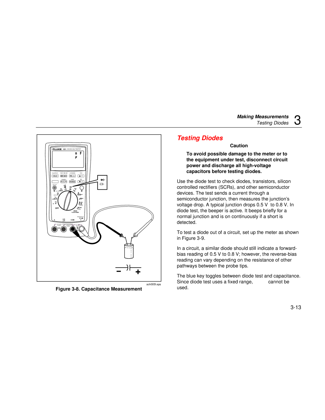
Figure 3-8. Capacitance Measurement
Testing Diodes
Caution
To avoid possible damage to the meter or to the equipment under test, disconnect circuit power and discharge all
Use the diode test to check diodes, transistors, silicon controlled rectifiers (SCRs), and other semiconductor devices. The test sends a current through a semiconductor junction, then measures the junction’s voltage drop. A typical junction drops 0.5 V to 0.8 V. In diode test, the beeper is active. It beeps briefly for a normal junction and is on continuously if a short is detected.
To test a diode out of a circuit, set up the meter as shown in Figure
In a circuit, a similar diode should still indicate a forward- bias reading of 0.5 V to 0.8 V; however, the
The blue key toggles between diode test and capacitance. Since diode test uses a fixed range, R cannot be used.