Troubleshooting 7

Manual Tests for Fault Isolation

7-5. Problems 1 or 2: Fault at Power-Up or When Entering Voltage Standby

Proceed as follows to isolate the problem in these conditions:

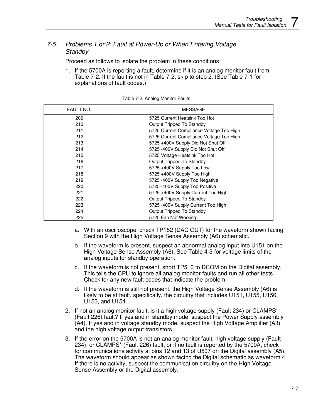
1.If the 5700A is reporting a fault, determine if it is an analog monitor fault from Table 7-2. If the fault is not in Table 7-2, skip to step 2. (See Table 7-1 for explanations of fault codes.)


Table 7-2. Analog Monitor Faults


FAULT NO.


MESSAGE


209

5725

Current Heatsink Too Hot

210


Output Tripped To Standby

211

5725

Current Compliance Voltage Too High

212

5725

Current Compliance Voltage Too High

213

5725

+400V

Supply Did Not Shut Off

214

5725

-400V

Supply Did Not Shut Off

215

5725

Voltage Heatsink Too Hot

216


Output Tripped To Standby

217

5725

+400V

Supply Too Low

218

5725

+400V

Supply Too High

219

5725

-400V

Supply Too Negative

220

5725

-400V

Supply Too Positive

221

5725

+400V

Supply Current Too High

222


Output Tripped To Standby

223

5725

-400V

Supply Current Too High

224


Output Tripped To Standby

225

5725

Fan Not Working

a.With an oscilloscope, check TP152 (DAC OUT) for the waveform shown facing Section 9 with the High Voltage Sense Assembly (A6) schematic.

b.If the waveform is present, suspect an abnormal analog input into U151 on the High Voltage Sense Assembly (A6). See Table 4-3 for voltage limits of the analog inputs for standby operation.

c.If the waveform is not present, short TP510 to DCOM on the Digital assembly. This tells the CPU to ignore all analog monitor faults and run all other tests. Check for any new fault codes that indicate the problem.

d.If the waveform is still not present, the High Voltage Sense Assembly (A6) is likely to be at fault, specifically, the circuitry that includes U151, U155, U156, U153, and U154.

2.If not an analog monitor fault, is it a high voltage supply (Fault 234) or CLAMPS* (Fault 226) fault? If yes and in standby mode, suspect the Power Supply assembly (A4). If yes and in voltage standby mode, suspect the High Voltage Amplifier (A3) and the high voltage output transistors.

3.If the error on the 5700A is not an analog monitor fault, high voltage supply (Fault 234), or CLAMPS* (Fault 226) fault, or if no fault is reported by the 5700A, check for communications activity at pins 12 and 13 of U507 on the Digital assembly (A5). The waveform should appear as shown facing the Digital schematic as waveform 4. If there is no activity, suspect the communication circuitry on the High Voltage Sense Assembly or the Digital assembly.

7-7

Page 137
Image 137
Fluke 5725A instruction manual Analog Monitor Faults, Fault no Message

5725A specifications

The Fluke 5725A is a high-performance, multifunctional temperature calibration source designed to meet the demanding requirements of laboratory and industrial environments. Renowned for its accuracy, reliability, and versatility, the 5725A serves as a powerful tool for engineers and technicians engaged in temperature calibration processes.

At the core of the 5725A is its advanced measurement technology, which allows for precision temperature calibrations across a wide range. With an operating temperature range from -200°C to 660°C, it caters to various applications, making it suitable for calibrating thermocouples, resistance temperature detectors (RTDs), and other temperature measurement devices.

One of the standout features of the Fluke 5725A is its outstanding accuracy, boasting a specified uncertainty of just ±0.15°C. This level of precision ensures that users can maintain compliance with regulatory standards and regulatory requirements in fields such as aerospace, pharmaceuticals, and manufacturing.

The Fluke 5725A is equipped with dual-channel capabilities, allowing users to calibrate two devices simultaneously. This enhances productivity by minimizing downtime and optimizing workflow efficiency. The intuitive touchscreen interface simplifies operations, enabling users to view measurements, set up test parameters, and access historical data with ease.

Versatile connectivity options such as USB and Ethernet enable seamless integration into existing systems and allow for data transfer, remote control, and configuration. This feature empowers technicians to conduct calibrations efficiently, whether on-site or remotely.

The robust design of the Fluke 5725A ensures its durability in demanding environments. Built with high-quality materials, it is resistant to shocks and vibrations, making it suitable for use in manufacturing plants and laboratories where equipment may be subjected to harsh conditions.

Another notable characteristic of the 5725A is its ability to generate stable temperature outputs with minimal drift, contributing to consistency in calibration results. Its built-in self-test functionality helps ensure that the unit remains in peak operating condition, giving users confidence in their calibration processes.

In summary, the Fluke 5725A is a top-tier temperature calibration source that excels in accuracy, reliability, and user-friendliness. Whether in laboratory settings or industrial applications, its advanced technologies and features make it an essential tool for professionals tasked with maintaining precision in temperature measurements.