Ti20
Users Manual
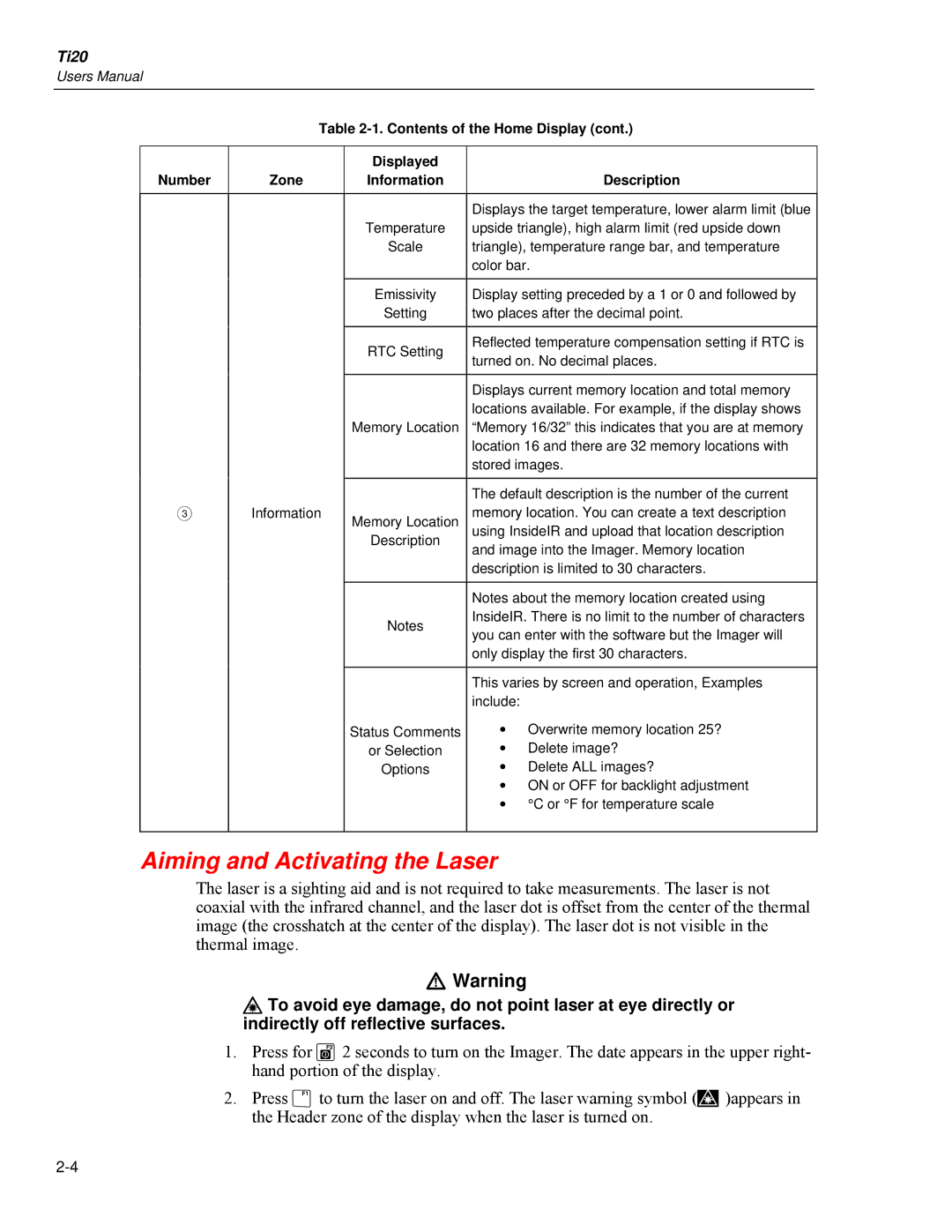
Table
Number
Zone
Displayed
Information
Description
C
Information
| Displays the target temperature, lower alarm limit (blue | ||
Temperature | upside triangle), high alarm limit (red upside down | ||
Scale | triangle), temperature range bar, and temperature | ||
| color bar. | ||
|
| ||
Emissivity | Display setting preceded by a 1 or 0 and followed by | ||
Setting | two places after the decimal point. | ||
|
| ||
RTC Setting | Reflected temperature compensation setting if RTC is | ||
turned on. No decimal places. | |||
| |||
|
| ||
| Displays current memory location and total memory | ||
| locations available. For example, if the display shows | ||
Memory Location | “Memory 16/32” this indicates that you are at memory | ||
| location 16 and there are 32 memory locations with | ||
| stored images. | ||
|
| ||
| The default description is the number of the current | ||
Memory Location | memory location. You can create a text description | ||
using InsideIR and upload that location description | |||
Description | and image into the Imager. Memory location | ||
| |||
| description is limited to 30 characters. | ||
|
| ||
| Notes about the memory location created using | ||
Notes | InsideIR. There is no limit to the number of characters | ||
you can enter with the software but the Imager will | |||
| |||
| only display the first 30 characters. | ||
|
| ||
| This varies by screen and operation, Examples | ||
| include: |
| |
Status Comments | • Overwrite memory location 25? | ||
or Selection | • | Delete image? | |
Options | • | Delete ALL images? | |
| • ON or OFF for backlight adjustment | ||
| • °C or °F for temperature scale | ||
|
|
| |
Aiming and Activating the Laser
The laser is a sighting aid and is not required to take measurements. The laser is not coaxial with the infrared channel, and the laser dot is offset from the center of the thermal image (the crosshatch at the center of the display). The laser dot is not visible in the thermal image.
WWarning
* To avoid eye damage, do not point laser at eye directly or indirectly off reflective surfaces.
1.Press for G2 seconds to turn on the Imager. The date appears in the upper right- hand portion of the display.
2.Press Fto turn the laser on and off. The laser warning symbol (J)appears in the Header zone of the display when the laser is turned on.
