24-Hour Service Hotline
andPartsManualService,Operation,Installation
FRYERS
8196004
DANGER
Never spray the fryer with water or use water jets to clean the fryer
NOTICE TO U.S. CUSTOMERS
NOTICE TO OWNERS OF UNITS EQUIPPED WITH COMPUTERS U.S
CANADA
Installation, Operation, Service, and Parts Manual TABLE OF CONTENTS
Navy Surface Ship Electric Fryers
NAVY SURFACE SHIP ELECTRIC FRYERS CHAPTER 1 INTRODUCTION
1.2 Safety Information
1.1 General
1.4 Shipping Damage Claim Procedure
1.5 Service Information
1.3 Controller Information
RETAIN AND STORE THIS MANUAL IN A SAFE PLACE FOR FUTURE USE
2.1 Introduction
NAVY SURFACE SHIP ELECTRIC FRYERS CHAPTER 2 INSTALLATION INSTRUCTIONS
Do not block the area around the base or under the fryers
2.2 Power Requirements
Do not connect the contacts in series
Do not connect more than one fryer to each set of contacts
The contacts CANNOT have an external voltage applied
2.5 Dimensions and Weights
2.3 Installation
2.4 After Fryers Are Anchored At the Frying Station DANGER
2-Fryer Battery
Single Fryer
FRONT HANDLE
BACK OF FRYER UNIT
3-Fryer Battery
4-Fryer Battery
2.470
62.55
3.1 Equipment Setup and Shutdown Procedures
NAVY SURFACE SHIP ELECTRIC FRYERS CHAPTER 3 OPERATING INSTRUCTIONS
Shutdown
3.2 Operation of the Solid-State Analog Controller
DESCRIPTION
HIGH-LIMIT TEST PROCEDURE
properly filled with oil. See Section CONTROLLER OPERATING PROCEDURE
The analog controller has no timing features. The operator must monitor shake and pull times
5. Place the controller power switch in the OFF position
4.1 Introduction
NAVY SURFACE SHIP ELECTRIC FRYERS CHAPTER 4 FILTRATION INSTRUCTIONS
4.2 Preparing the Filter for Use
4.3 Operation of the Filter DANGER
3. Place the metal filter screen in the center of the bottom of the pan, then lay a sheet of filter paper on top of the screen, over- lapping on all sides
2. Remove the basket support rack from the frypot, raise the element assembly to the up position, and snap the Power Shower into position
4.4 Draining and Disposing of Waste Oil
6. Lower the elements into the frypot and reinstall the basket support rack. Ensure the drain valve is fully closed. If the drain valve is not fully closed, the fryer will not operate. Turn the fryer ON and allow the cooking oil to reach setpoint
NAVY SURFACE SHIP ELECTRIC FRYERS CHAPTER 5 PREVENTIVE MAINTENANCE
5.1 Cleaning the Fryer DANGER
5.1.1 Clean Inside and Outside of the Fryer Cabinet - Daily
5.1.2 Clean the Built-in Filtration System - Daily
Boiling-Out the Frypot
5.1.3 Clean the Frypot and Heating Elements - Weekly DANGER
2. Press the fryer ON/OFF switch to the ON position
5.2 Check Calibration of Temperature Control Knob - Monthly
5.1.4 Clean Detachable Parts and Accessories - Weekly
5. Turn the fryer ON/OFF switchs to the OFF position
Fryer
5.3 Annual/Periodic System Inspection
Built-In Filtration System
− Verify that filter pan cover is present and properly installed
Check filtration system integrity as follows
NAVY SURFACE SHIP ELECTRIC FRYERS CHAPTER 6 OPERATOR TROUBLESHOOTING
6.1 Introduction
Verify that power is connected and that circuit breakers are on
Verify that frypot drain valves are fully closed
Problem
6.2 Troubleshooting 6.2.1 Control and Heating Problems
Probable Causes
Corrective Action
Probable Causes
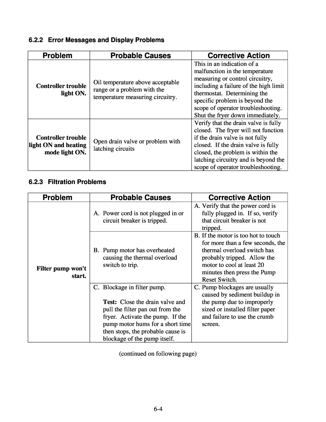
6.2.2 Error Messages and Display Problems
6.2.3 Filtration Problems
Filter pump runs
6.3 Replacing the Controller or Controller Wiring Harness
7.1 General
NAVY SURFACE SHIP ELECTRIC FRYERS CHAPTER 7 SERVICE PROCEDURES
7.2 Replacing a Controller
7.3 Replacing Component Box Components
DO NOT drain more than one full frypot into the SDU at one time
7.4 Replacing a Temperature Probe or High-Limit Thermostat
1. Remove the filter pan and lid from the unit. Drain the frypots into a Shortening Disposal Unit SDU or other appropriate container
7.5 Replacing a Heating Element
viewed from the rear
7.6 Replacing Contactor Box Components
7.7 Replacing a Frypot
12. Disconnect the oil return flexlines at the frypot ends
22. Reinstall the drain tube assembly
7.8.2 Replacing the Filter Motor, Filter Pump, and Related Components
Sediment Particle Oil Flow Up for reverse Down for forward
7-10
7.8.3 Replacing the Filter Transformer or Filter Relay
7.9 Interface Board Diagnostic Chart
Diagnostic LED Legend
Meter Setting
Test
7.10 Wiring Diagram, System
Refer to page 2-2 for power requirements
7-13
8051421F
7.11 Wiring Diagram, Contactor Box
7-14
7.12 Components Description of Operation
NAVY SURFACE SHIP ELECTRIC FRYERS CHAPTER 8 PARTS LIST
Accessories
8.2 Cabinetry
Side, Cabinet Single Left Use 212-8479 for Rt. Side
Handle Grab Rail For handle end use
Top Cap Single Top cap for five station fryer shown
106-3036SP
8.2.2 Cabinet Bases, Braces, and Associated Parts
Upright Assembly, Left Use 106-3828 for singles
Upright Assembly, Right Use 106-3829 for singles
Channel, Base Rear Use 106-4901 for singles base assembly
8.2.2 Cabinet Bases, Braces, and Associated Parts cont
8.3 Drain System Components
8.3.1 Drain Tube Sections and Associated Parts
See Page 8-10 for Drain
8.3.1.1 Euro-Look Drain Tube Section and Associated Parts
Valve Detail
8.3.1.1 Euro-Look Drain Tube Section and Associated Parts cont
EURO-LOOK
8.3.2 Drain Valve Assembly and Component Parts
Page
ITEM EURO-LOOK
8.4 Electronics and Wiring Components 8.4.1.1 Single Component Box
8.4.1.2 Multiple Vat Component Boxes
8.4.2.1 Single Contactor Box
8.4.2.2 Multiple Vat Contactor Boxes
8.4.3 Heating Element Assembly and Associated Parts
8.4.3 Heating Element Assembly and Associated Parts cont
Wiring
8.4.5.1 Contactor Box Wiring Assembly - 12-Pin Full-Vat C-1
8.4.5.2 Contactor Box Wiring Assemblies - 6-Pin Left Element
8.4.4
8.4.5.3 Contactor Box Wiring Assemblies - 9-Pin Right Element
8.4.5.4 Single Contactor Box Wiring Assembly
8.4.5.5 Main Wiring Harness
P/N 106-3467SP 14/17kW or P/N 106-2472SP 22kW
8.4.5.6 Single Main Wiring Harness
8.4.5.7 Component Box Wiring Harness - 15-Pin
8.4.5.8 Single Component Box Wiring Harness - 15-Pin
8.4.5.9 Single Component Box Wiring Harness - 15-Pin without Filter
8.5 Filtration System Components
8.5.1 FPH117/122 Filtration Components
8.5.1 FPH117/122 Filtration Components cont
units were configured this way
8.5.2 FPH217/317 Multiple Battery Filtration System Components
NOTE Some early production
8.5.2 FPH217/317 Multiple Battery Filtration System Components cont
STANDARD
EURO-LOOK
Lid for units built before Feb 04, use
Frypot P/N 823-2451SP
8.6 Frypot Assembly and Thermostat
Thermostat P/N
8.7 Oil Return System Components
8.7 Oil Return System Components cont
8.8 WIRING CONNECTORS, PIN TERMINALS, AND POWER CORDS
Power Cords
Connectors
COMPONENT
SERVICE HOTLINE
Shipping Address 8700 Line Avenue, Shreveport, Louisiana
FAX Parts
Tech Support