5.6 Timing
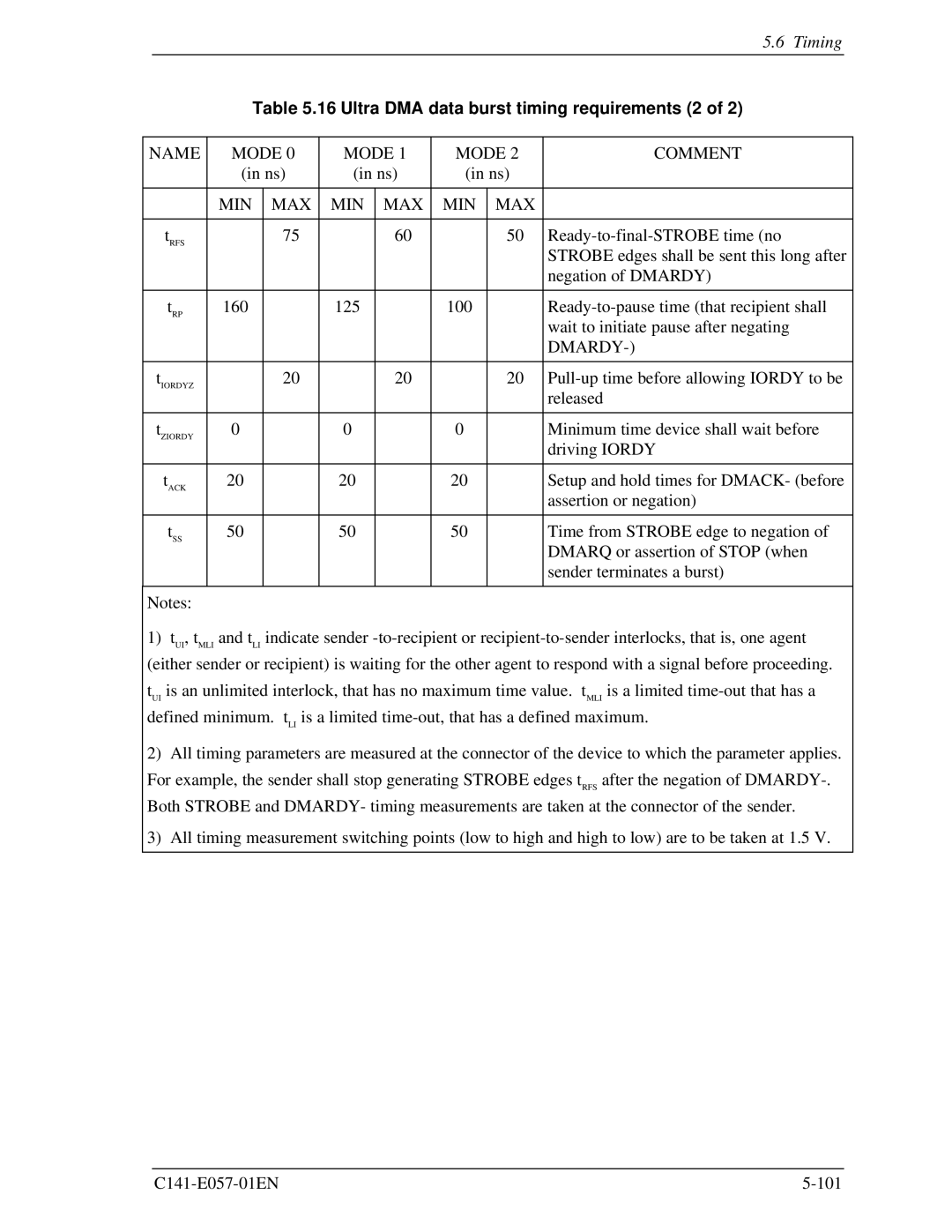
Table 5.16 Ultra DMA data burst timing requirements (2 of 2)
NAME | MODE 0 | MODE 1 | MODE 2 | COMMENT | |||
| (in ns) | (in ns) | (in ns) |
| |||
|
|
|
|
|
|
|
|
| MIN | MAX | MIN | MAX | MIN | MAX |
|
|
|
|
|
|
|
|
|
tRFS |
| 75 |
| 60 |
| 50 | |
|
|
|
|
|
|
| STROBE edges shall be sent this long after |
|
|
|
|
|
|
| negation of DMARDY) |
|
|
|
|
|
|
|
|
tRP | 160 |
| 125 |
| 100 |
| |
|
|
|
|
|
|
| wait to initiate pause after negating |
|
|
|
|
|
|
|
|
|
|
|
|
|
|
|
|
tIORDYZ |
| 20 |
| 20 |
| 20 | |
|
|
|
|
|
|
| released |
|
|
|
|
|
|
|
|
tZIORDY | 0 |
| 0 |
| 0 |
| Minimum time device shall wait before |
|
|
|
|
|
|
| driving IORDY |
|
|
|
|
|
|
|
|
tACK | 20 |
| 20 |
| 20 |
| Setup and hold times for DMACK- (before |
|
|
|
|
|
|
| assertion or negation) |
|
|
|
|
|
|
|
|
tSS | 50 |
| 50 |
| 50 |
| Time from STROBE edge to negation of |
|
|
|
|
|
|
| DMARQ or assertion of STOP (when |
|
|
|
|
|
|
| sender terminates a burst) |
|
|
|
|
|
|
|
|
Notes: |
|
|
|
|
|
|
|
1)tUI, tMLI and tLI indicate sender
2)All timing parameters are measured at the connector of the device to which the parameter applies. For example, the sender shall stop generating STROBE edges tRFS after the negation of
3)All timing measurement switching points (low to high and high to low) are to be taken at 1.5 V.