|
| 5.1 Physical Interface |
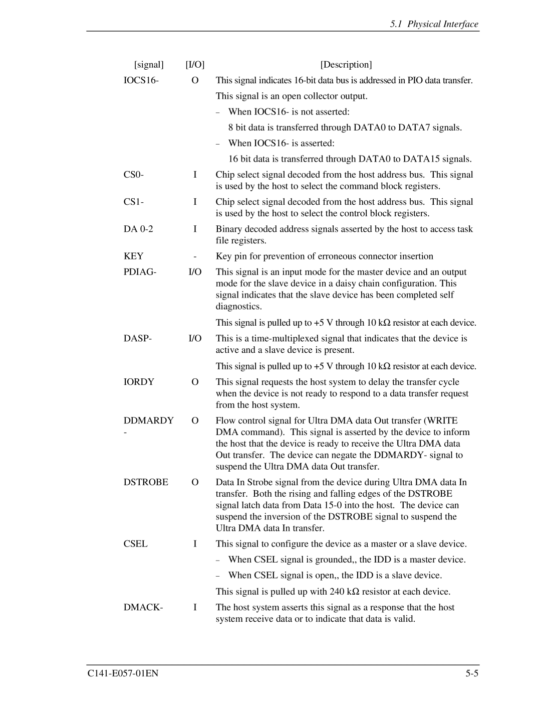
[signal] | [I/O] | [Description] |
IOCS16- | O | This signal indicates |
|
| This signal is an open collector output. |
|
| − When IOCS16- is not asserted: |
|
| 8 bit data is transferred through DATA0 to DATA7 signals. |
|
| − When IOCS16- is asserted: |
|
| 16 bit data is transferred through DATA0 to DATA15 signals. |
CS0- | I | Chip select signal decoded from the host address bus. This signal |
|
| is used by the host to select the command block registers. |
CS1- | I | Chip select signal decoded from the host address bus. This signal |
|
| is used by the host to select the control block registers. |
DA | I | Binary decoded address signals asserted by the host to access task |
|
| file registers. |
KEY | - | Key pin for prevention of erroneous connector insertion |
PDIAG- | I/O | This signal is an input mode for the master device and an output |
|
| mode for the slave device in a daisy chain configuration. This |
|
| signal indicates that the slave device has been completed self |
|
| diagnostics. |
|
| This signal is pulled up to +5 V through 10 kΩ resistor at each device. |
DASP- | I/O | This is a |
|
| active and a slave device is present. |
|
| This signal is pulled up to +5 V through 10 kΩ resistor at each device. |
IORDY | O | This signal requests the host system to delay the transfer cycle |
|
| when the device is not ready to respond to a data transfer request |
|
| from the host system. |
DDMARDY | O | Flow control signal for Ultra DMA data Out transfer (WRITE |
- |
| DMA command). This signal is asserted by the device to inform |
|
| the host that the device is ready to receive the Ultra DMA data |
|
| Out transfer. The device can negate the DDMARDY- signal to |
|
| suspend the Ultra DMA data Out transfer. |
DSTROBE | O | Data In Strobe signal from the device during Ultra DMA data In |
|
| transfer. Both the rising and falling edges of the DSTROBE |
|
| signal latch data from Data |
|
| suspend the inversion of the DSTROBE signal to suspend the |
|
| Ultra DMA data In transfer. |
CSEL | I | This signal to configure the device as a master or a slave device. |
|
| − When CSEL signal is grounded,, the IDD is a master device. |
|
| − When CSEL signal is open,, the IDD is a slave device. |
|
| This signal is pulled up with 240 kΩ resistor at each device. |
DMACK- | I | The host system asserts this signal as a response that the host |
|
| system receive data or to indicate that data is valid. |