4.6 Read/write Circuit
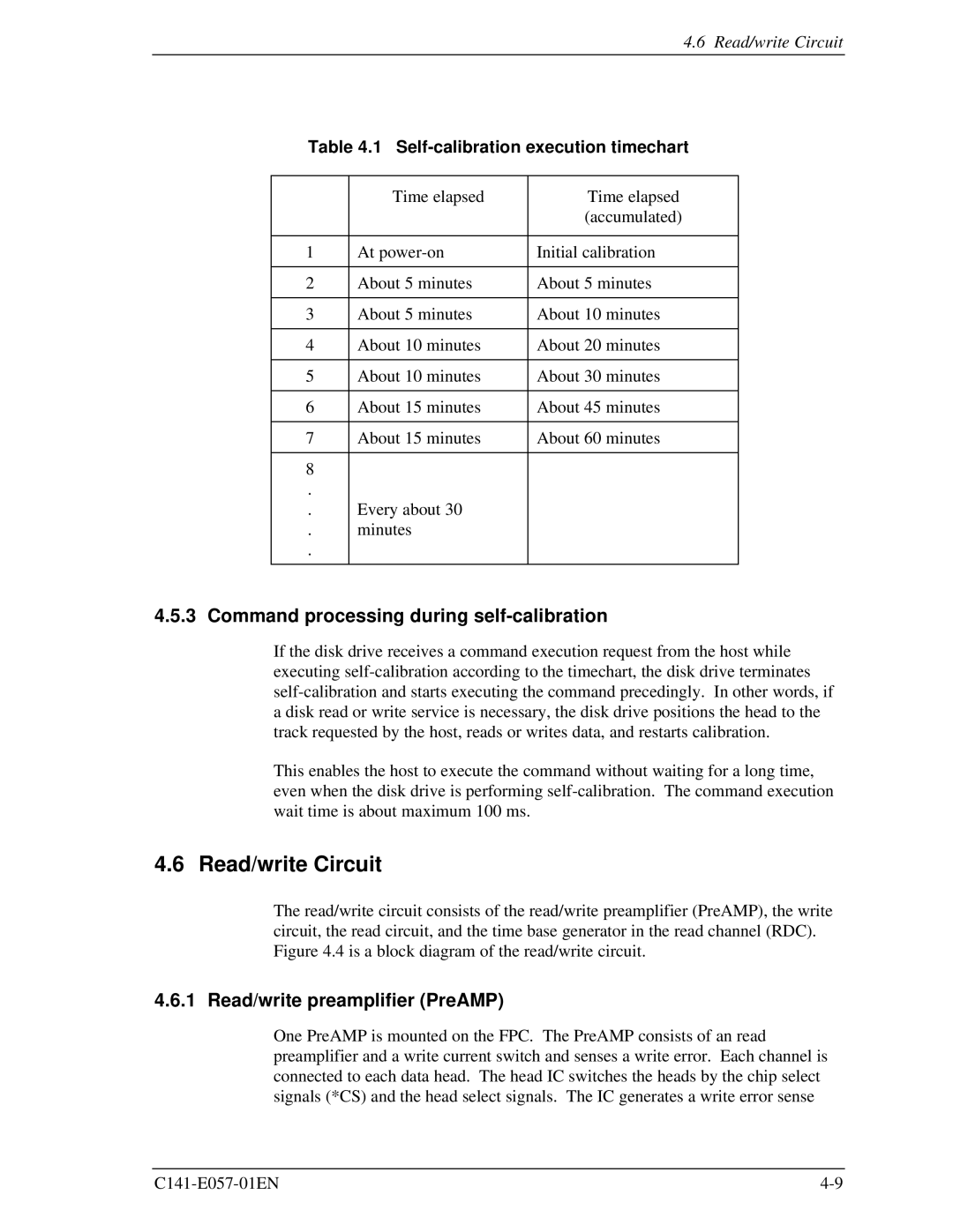
Table 4.1 Self-calibration execution timechart
| Time elapsed | Time elapsed |
|
| (accumulated) |
|
|
|
1 | At | Initial calibration |
|
|
|
2 | About 5 minutes | About 5 minutes |
|
|
|
3 | About 5 minutes | About 10 minutes |
|
|
|
4 | About 10 minutes | About 20 minutes |
|
|
|
5 | About 10 minutes | About 30 minutes |
|
|
|
6 | About 15 minutes | About 45 minutes |
|
|
|
7 | About 15 minutes | About 60 minutes |
|
|
|
8 |
|
|
. |
|
|
. | Every about 30 |
|
. | minutes |
|
. |
|
|
|
|
|
4.5.3 Command processing during self-calibration
If the disk drive receives a command execution request from the host while executing
This enables the host to execute the command without waiting for a long time, even when the disk drive is performing
4.6 Read/write Circuit
The read/write circuit consists of the read/write preamplifier (PreAMP), the write circuit, the read circuit, and the time base generator in the read channel (RDC). Figure 4.4 is a block diagram of the read/write circuit.
4.6.1 Read/write preamplifier (PreAMP)
One PreAMP is mounted on the FPC. The PreAMP consists of an read preamplifier and a write current switch and senses a write error. Each channel is connected to each data head. The head IC switches the heads by the chip select signals (*CS) and the head select signals. The IC generates a write error sense
