Interface
(9)Command Field
The Command Field contains a command code being sent to the device. After this field is written, the command execution starts immediately.
Table 5.3 lists the executable commands and their command codes. This table also lists the necessary parameters for each command which are written to certain fields before the Command register is written.
(10) Device Control Field
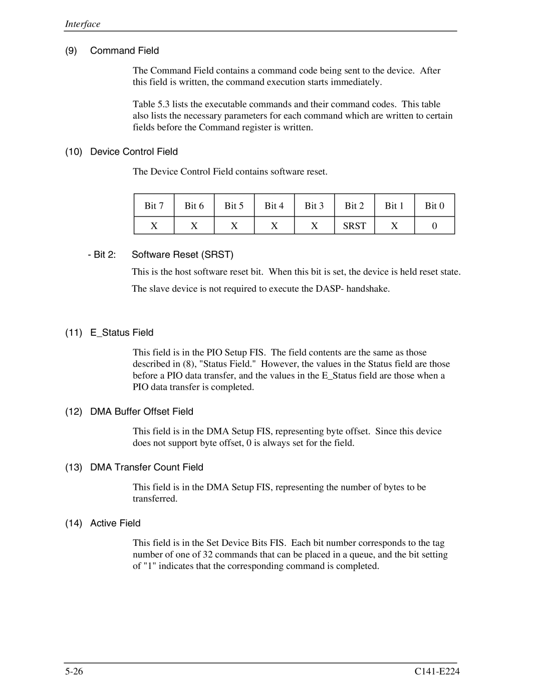
The Device Control Field contains software reset.
Bit 7 | Bit 6 | Bit 5 | Bit 4 | Bit 3 | Bit 2 | Bit 1 | Bit | 0 |
|
|
|
|
|
|
|
|
|
X | X | X | X | X | SRST | X | 0 |
|
|
|
|
|
|
|
|
|
|
- Bit 2: Software Reset (SRST)
This is the host software reset bit. When this bit is set, the device is held reset state.
The slave device is not required to execute the DASP- handshake.
(11) E_Status Field
This field is in the PIO Setup FIS. The field contents are the same as those described in (8), "Status Field." However, the values in the Status field are those before a PIO data transfer, and the values in the E_Status field are those when a PIO data transfer is completed.
(12) DMA Buffer Offset Field
This field is in the DMA Setup FIS, representing byte offset. Since this device does not support byte offset, 0 is always set for the field.
(13) DMA Transfer Count Field
This field is in the DMA Setup FIS, representing the number of bytes to be transferred.
(14) Active Field
This field is in the Set Device Bits FIS. Each bit number corresponds to the tag number of one of 32 commands that can be placed in a queue, and the bit setting of "1" indicates that the corresponding command is completed.