Color Scanning Sonar
00014857415
Safety Instructions
Projected Raising Lowering Mm stroke Max kt
System Configuration
Iii
Standard supply
Optional Equipment
Hull Unit
Mounting considerations
Hull unit mounting location
Maintenance space, example sonar compartment
Shortening the retraction tank
Guidelines for shortening the retraction tank
Remarks for installation of retraction tank
How to install reinforcement ribs
Installing hull unit on retraction tank
Installation of hull unit
Installing stays anti-vibration measure
Proper installation of stays
Proper and improper stay installation methods
Processor Unit
Mounting considerations
Processor unit, rear view
Mounting procedure
Control Unit
Processor unit
Rubber feet
How to attach KB fixing plate
Mounting without KB fixing plate
Control unit
Mounting with KB fixing plate
Control unit, cover removed
Control unit, side view
Transceiver Unit
Grounding the Equipment
Transceiver unit
Transceiver unit, junction box Use copper strap supplied
Installing the Attachment Flange option
Procedure
Attachment flange Type OP10-27, Code no
Cable Extension Kit option
Junction box
Installing the Attachment Kit option
Attachment kit Type OP10-24, Code no
Installation of attachment kit
How to Use the Crimping Tool, Pin Extractor
How to use the crimping tool
How to use the pin extractor
Crimping tool, contact pin, pin extractor
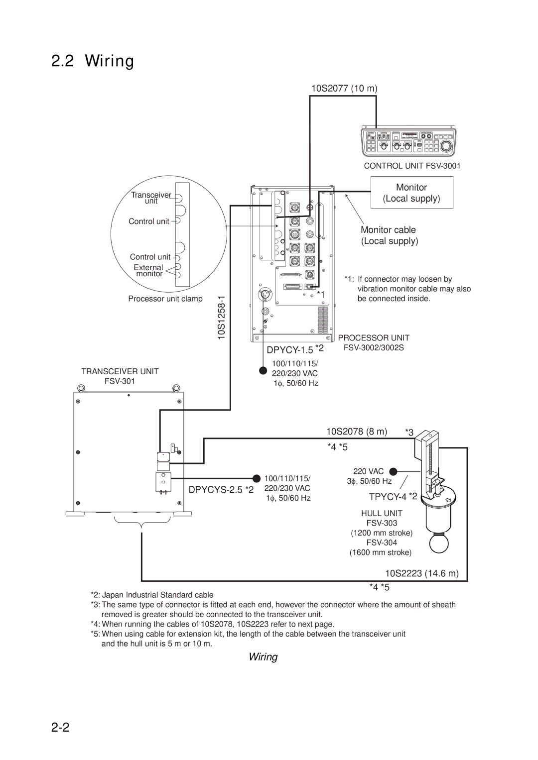
Wiring
Wiring
Transceiver unit side
1 10S1258-1 cable
Cable type 10S1258-1, sectional view
Fabrication of connector 00-8016-038-313761HV CN-A101
Fabrication of cable for connector 00-8016-038-313761HV
Assembling 38P connector
Positioning guide pins
Power cable
Assembling connector NCS-253-P
Control cable
Cable list
Sectional view of cables
Gyro
Menu setting
Synchronizing with echo sounder or other sonar
For current driven KP input
For voltage driven KP 12 V input
Fabrication of connector 00-8016-038-313761HV CN-B101
Fabrication of cable for 00-8016-038-313761HV
Transceiver unit, inside view
CN-B101 CN-B102
Fabrication of power cable type DPYCYS-2.5 TB-B101
Hull control cable 10S2078
Fabrication of cable type DPYCYS-2.5
Wiring in transceiver unit
Transceiver unit, top view
Cable Extension Kit
Junction box
Junction box, cover removed
Signal cable 10S2240 connects to Junction BOX display side
Raise/Lower control box
Raise/lower control box, cover removed
Power cable fabrication
Input Voltage and Fuses
Input voltage
Fuses
Marking the label
Hull Unit Check
Main menu
Others menu
Initial Setting menu
Test menu
How to check the hull unit
Transducer switches of the control unit
Control unit in hull unit
Page
Heading Adjustment
Heading adjustment
System menu
Others menu, Heading Adjust
Configuring Own Ship Mark
OWN Ship Mark menu, setting window
OWN Ship Mark menu
Ship shape description
Interface Setting menu
Interface Setting menu
Other System Menu Items
EXT Data Setting menu
EXT Data Setting menu
Data sentences Nmea 0183, Furuno proprietary
Others menu
ES Draft Offset
Cone Board Setting in the Processor Unit
Adjustment of signal level echo sounder connected
Adjusting the volume of the audio alarm
DIP Switch Setting
1 CIF2/NMEA2 connector interface selection
Processor unit, inside view
Ifes Board 10P6983
Choosing echosounder signal
This page intentionally left blank
Name Type Code No Qty Remarks
Processor unit, front view
Wiring between processor unit and CS-120A
GND
Dcon Board 10P6984 or 10P6984A
This page intentionally left blank
Packing List
FSV-301
58����
58���� 58��������58��������58�������
付属品表
52#4�2#465�.+56�14�
52��������
Page
Page
Page
Hatai
Hatai
Hatai
Hatai
Hatai
Page
Page
This page is intentionally left blank
Color Scanning Sonar
Miyosi