2.4.4Wiring in transceiver unit
1.Open the transceiver unit cover.
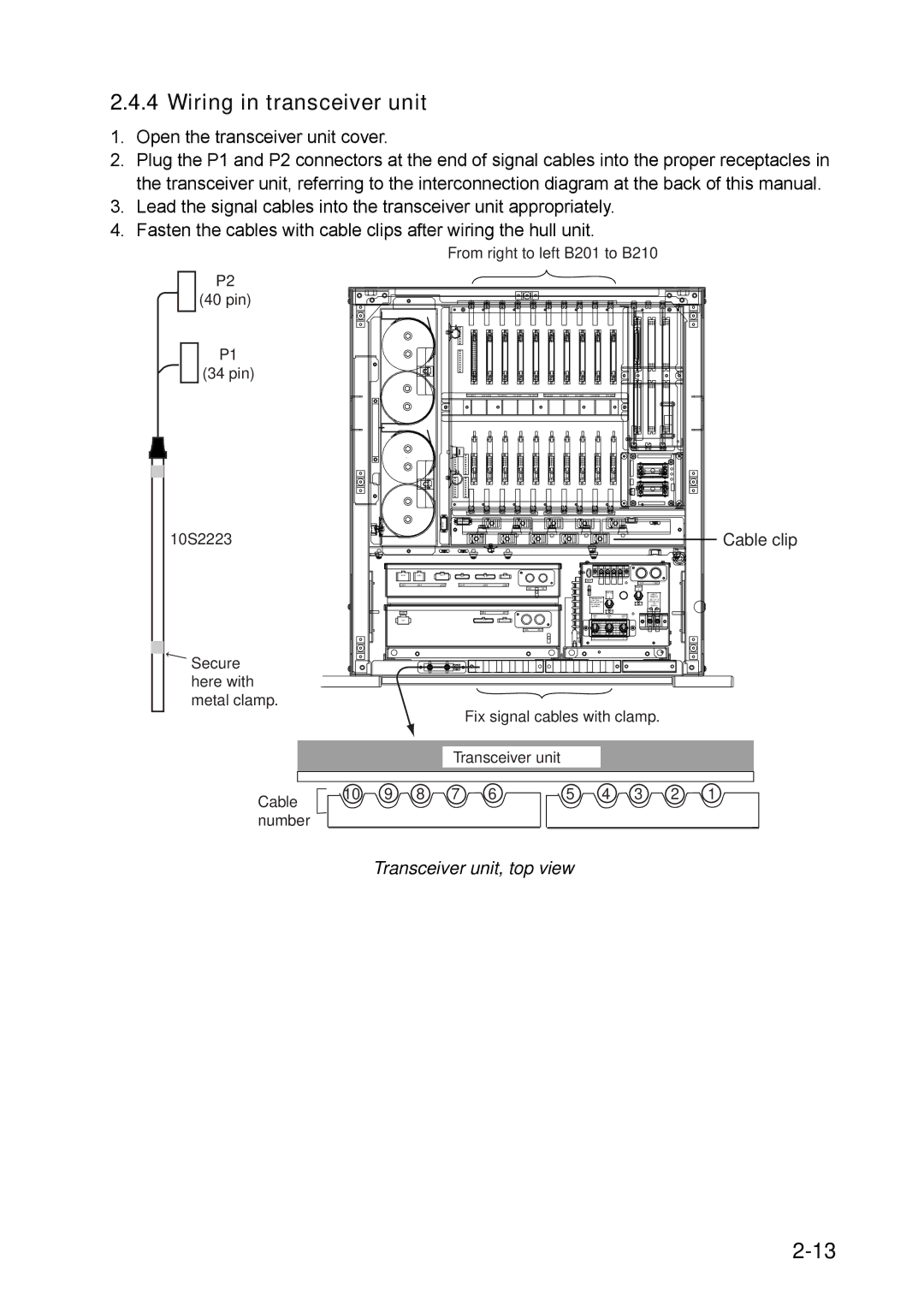
2.Plug the P1 and P2 connectors at the end of signal cables into the proper receptacles in the transceiver unit, referring to the interconnection diagram at the back of this manual.
3.Lead the signal cables into the transceiver unit appropriately.
4.Fasten the cables with cable clips after wiring the hull unit.
From right to left B201 to B210
P2
(40 pin)
P1
(34 pin)
|
69626963
10S2223 | Cable clip |
|
|
|
|
|
|
| J601 |
|
|
|
J201 | J202 | J203 | J204 | J205 | J206 |
|
|
|
|
|
|
|
|
|
| 5A |
| 5A |
|
|
|
|
|
|
|
|
|
|
| MAINTENANCE |
|
|
|
|
|
|
|
|
| Maintenance | I |
|
|
|
|
|
|
|
|
| Use Only. |
|
|
|
|
|
|
|
|
|
| (Should be OFF |
|
|
|
|
|
|
|
|
|
| for Normal |
|
|
|
|
|
|
|
|
|
| operation.) |
|
|
|
J301 |
|
|
| J302 | J303 |
|
|
|
|
|
|
|
|
|
|
|
| S603 | S604 |
| S605 |
|
|
|
|
|
|
| H | H |
| H |
|
|
|
|
|
|
| S604 | S605 | ||
|
|
|
|
|
|
| 100V | L | L | L |
|
|
|
|
|
|
| 110V | H | L | L |
|
|
|
|
| 15A | 15A | 115V | H | H | L |
|
|
|
|
| 220V | H | L | H | ||
|
|
|
|
|
|
| 230V | H | H | H |
|
|
|
|
|
|
| L | L |
| L |
F601 F602
MAIN
I
INPUT
100/110/115
/220/230 VAC
:15A
50/60Hz
1 2
Secure here with metal clamp.
Fix signal cables with clamp.
Transceiver unit
Cable | 10 | 9 | 8 | 7 | 6 | 5 | 4 | 3 | 2 | 1 |
|
|
|
|
|
|
|
|
|
|
number