1.5Operational modes
S3 | Maintenance |
S2 |
|
S1 |
|
AC Supply | S4 |
Battery |
|
Contactor | 24/36kVA Ratings |
LOAD
S3 | Maintenance |
S2 | S5 |
| |
| 480Y/277V |
S1
AC Supply
LOAD
| S4 |
| 208Y/120V |
Battery |
|
Contactor | 50/80kVA Ratings |
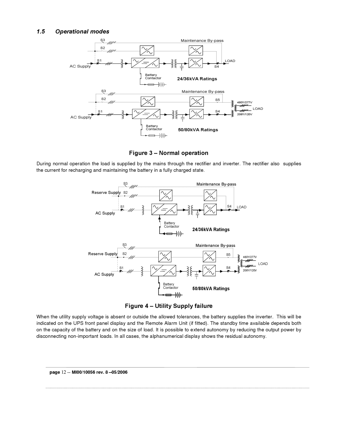
Figure 3 – Normal operation
During normal operation the load is supplied by the mains through the rectifier and inverter. The rectifier also supplies the current for recharging and maintaining the battery in a fully charged state.
S3 | Maintenance |
Reserve Supply | S2 |
|
|
S1 | S4 | LOAD | |
AC Supply |
|
|
|
|
| Battery |
|
|
| Contactor |
|
|
| 24/36kVA Ratings |
|
Reserve Supply
S3 | Maintenance |
S2 | S5 |
| 480Y/277V |
S1
AC Supply
LOAD
| S4 |
| 208Y/120V |
Battery |
|
Contactor | 50/80kVA Ratings |
Figure 4 – Utility Supply failure
When the utility supply voltage is absent or outside the allowed tolerances, the battery supplies the inverter. This will be indicated on the UPS front panel display and the Remote Alarm Unit (if fitted). The standby time available depends both on the capacity of the battery and on the size of load. It is possible to extend autonomy by reducing the output power by disconnecting
