11.0COMPUTER INTERFACE
11.1AS400
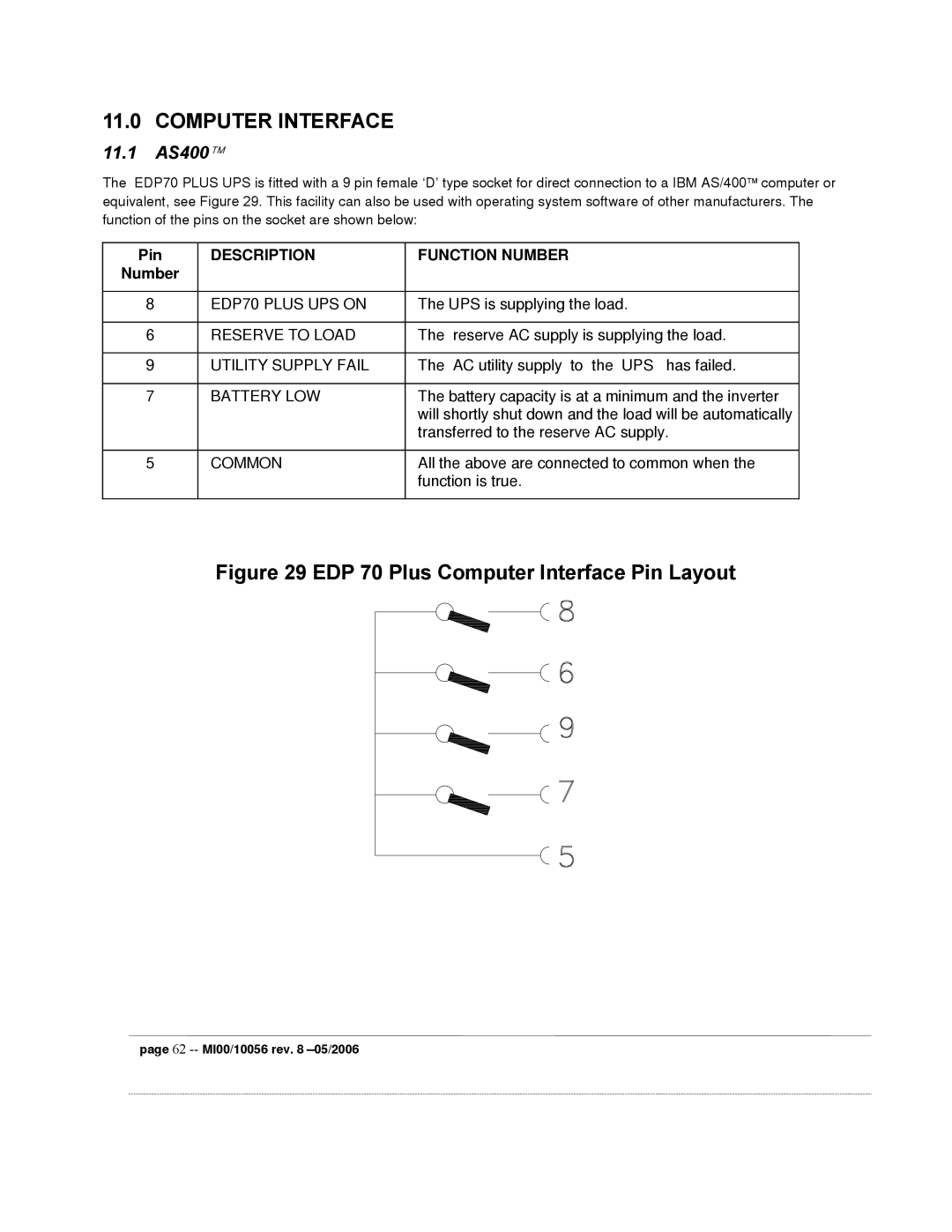
The EDP70 PLUS UPS is fitted with a 9 pin female ‘D’ type socket for direct connection to a IBM AS/400 computer or equivalent, see Figure 29. This facility can also be used with operating system software of other manufacturers. The function of the pins on the socket are shown below:
Pin | DESCRIPTION | FUNCTION NUMBER |
Number |
|
|
|
|
|
8 | EDP70 PLUS UPS ON | The UPS is supplying the load. |
|
|
|
6 | RESERVE TO LOAD | The reserve AC supply is supplying the load. |
|
|
|
9 | UTILITY SUPPLY FAIL | The AC utility supply to the UPS has failed. |
|
|
|
7 | BATTERY LOW | The battery capacity is at a minimum and the inverter |
|
| will shortly shut down and the load will be automatically |
|
| transferred to the reserve AC supply. |
|
|
|
5 | COMMON | All the above are connected to common when the |
|
| function is true. |
|
|
|
Figure 29 EDP 70 Plus Computer Interface Pin Layout
page 62