Manuals
/
Garmin
/
Computer Equipment
/
Power Supply
Garmin
EDP70
manual
Battery Cabinet Drawing for 50/80kVA Ratings
Models:
EDP70
1
23
67
67
Download
67 pages
37.68 Kb
20
21
22
23
24
25
26
27
Install
Silencing Audible Alarm
Maintenance
24kVA Standard Configuration
Resetting data loss manually
Access Plate
Battery Test Weekly
Emergency Procedure
Safety
Power History Down to Access
Page 23
Image 23
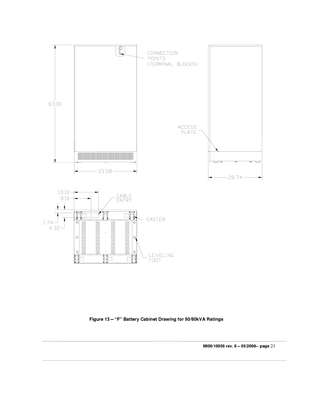
Figure 13 — “F” Battery Cabinet Drawing for 50/80kVA Ratings
MI00/10056 rev. 8 —
05/2006--
page
23
Page 22
Page 24
Page 23
Image 23
Page 22
Page 24
Contents
EDP70 Plus
2 --MI00/10056 rev -05/2006
Injuries Caused by Contact with Corrosive Liquids
Electrical Precautions
Emergency Procedure
Electric Shock
Contents
Maintenance and Spare Parts
Figures
Equipment Delivery and Storage
8 -- MI00/10056 rev -05/2006
Introduction
36kVA 480V/208V Configuration
24kVA Standard Configuration
36kVA Standard Configuration
RECTIFIER/INVERTER
24/36kVA Ratings
Contactor 24/36kVA Ratings
Safety
Eye goggles Rubber gloves Rubber apron Rubber boots
Storage
ALL Measurements are Millimeters and Inches
18 --MI00/10056 rev -05/2006
Cable Entry
Battery Cabinet Drawing for 24/36kVA Ratings
Battery Cabinet Drawing for 24/36kVA Ratings
Battery Cabinet Drawing for 50/80kVA Ratings
Battery Cabinet Drawing for 50/80kVA Ratings
Entry
Access Plate
Fuse
Cable
32.68
Connection
Points
40.16
BTU/H
Recommended wire sizes
UPS Type
= 2770 - - - e 0.125 h Tk / T0 T k
Connection
Uninterruptible Power System No Unauthorized Operation
#$# % # #% + ,+%
Indentor Moveable
AWG
M10
Nest Stationary Tool
S2 = Equipment Reserve Switch
Observe Polarities and Orientations
U1V1W1N PE U V W N U2V2W2 N
Front
RAU Female
Rear
36 --MI00/10056 rev -05/2006
36 24/30/36kVA Connections
QS2
QS1 QS4
Terminal board compartment
40 --MI00/10056 rev -05/2006
Rear
QS1 QS2 QS3 QS4 QS5
Signal connections Emergency Power Off
Controls
Right Control
Maintenance Bypass
SHUT-DOWN
Installing the EPO
Liquid Crystal Display
Silencing Audible Alarm
Mimic
Display Page Headings
RECT/BATT Alarms No Alarms Active
Inverter Alarms No Alarms Active
LOAD/RES Alarms No Alarms Active
Selected Language English
Battery Test Weekly
Power History Down to Access
Load F xx.x Hz Xxx V B xxx V C
Last Mains Failure xxd xxh xxm xxs
Inverter
Vdc xxx V Ib xxxx a
Inverter F xx.x Hz Xxx V B xxx V C xxx
Inverter F xx.x Hz AB xxx V BC xxx V CA xxx
Load
System Alarm
Abnormal operating mode messages
Main page Heading Alarms Message Condition
Stop DUE to Overload
Battery Discharging
Overload
RECTIFIER/BATTERY Alarms Message Condition
Inverter Alarms Message Condition
LOAD/RESERVE Alarms Message Condition
Power History Matrix
Power History
System normal message
Battery Test
Battery Autonomy Test
Resetting data loss manually
11.1 AS400
11.2 RS232
Safety
13.1 EDP70 PLUS/24/18/12 Battery Installation/Start-up
13.2 EDP70 PLUS/24/18/12 Optional Battery Cubicle
EDP70 PLUS/24/18/12 Internal Battery Shelves
13.4 EDP70 Plus above 24KVA Battery Cubicle
13.3 EDP70 Plus above 24KVA Battery Installation/Start-up
EDP70 Plus System LOG
Top
Page
Image
Contents