Magnum 6K25 Managed Fiber Switch | Installation and User Guide (04/06) |
3.2Connecting Ethernet Media
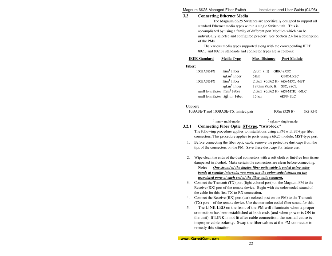
The Magnum 6K25 Switches are specifically designed to support all standard Ethernet media types within a single Switch unit. This is accomplished by using a family of different port Modules which can be individually selected and configured
The various media types supported along with the corresponding IEEE
802.3 and 802.3u standards and connector types are as follows: | |||
IEEE Standard | Media Type | Max. Distance | Port Module |
Fiber: | mm1 Fiber |
|
|
220m ( ft) | |||
| sgl.m2 Fiber | 5Km | |
mm1 Fiber | 2.0km (6,562 ft) | ||
| sgl.m2 Fiber | 18.0km (95K ft) | SSC, SSCL |
small form factor | mm1 Fiber | 2.0km (6,562 ft) | |
small form factor | sgl.m1 Fiber | 15 km | 6KP8- SLC |
Copper: |
|
|
100m (328 ft) | ||
1 mm = | 2 sgl.m = |
|
3.2.1Connecting Fiber Optic ST-type, “twist-lock”
The following procedure applies to installations using a PM with
1.Before connecting the fiber optic cable, remove the protective dust caps from the tips of the connectors on the PM. Save these dust caps for future use.
2.Wipe clean the ends of the dual connectors with a soft cloth or
Note: One strand of the duplex fiber optic cable is coded using color bands at regular intervals; you must use the
3.Connect the Transmit (TX) port (light colored post) on the Magnum PM to the Receive (RX) port of the remote device. Begin with the
4.Connect the Receive (RX) port (dark colored post on the PM) to the Transmit
(TX) port of the remote device. Use the
5.The LINK LED on the front of the PM will illuminate when a proper connection has been established at both ends (and when power is ON in the unit). If LINK is not lit after cable connection, the normal cause is improper cable polarity. Swap the fiber cables at the PM connector to remedy this situation.
www. GarrettCom . com
22