Magnum 6K25 Managed Fiber Switch | Installation and User Guide (04/06) |
Sec.1.2 for all the various P6K PoE modules option.
The LEDs on 6KP8-RJ45- PoE module are slightly different compared to regular (non-PoE) RJ-45 modules as shown in Fig 2. When the PoE port is in use, the PoE LED is ON when connected properly to a 803.af compliant PD device on that port. When non-PoE devices are connected, the PoE LED is OFF. Operation of Ethernet data traffic is not affected by PoE.
LINK and ACTIVITY LEDS are combined on the PoE modules into one LED that is marked as LINK/ACT, as shown in the diagram.
2.2.6Six-Port “4 + 2”Combo Modules, 4@ 10/100 RJ-45 and 2@100Mb fiber 4@RJ-45 + 2@ 100Mb ST or SC
The combo six-port modules are combinations of copper and fiber media, available as
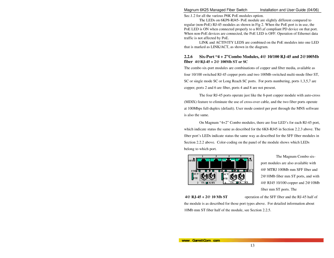
four 10/100 switched RJ-45 copper ports and two 100Mb switched multi-mode fiber ST, SC or single mode SC or Long Reach SC ports. For ports numbering, ports 1,3,5,7 are copper, ports 2 and 6 are fiber, ports 4 and 8 are not present.
The four RJ-45 ports operate just like the 8-port copper module with auto-cross (MDIX) feature to eliminate the use of cross-over cable, and the two fiber ports operate at 100Mbps full-duplex (default). User mode control per port through the MNS software is also the same.
On Magnum “4+2” Combo modules, there are four LED’s for each RJ-45 port, which indicate status the same as described for the 6K8-RJ45 in Section 2.2.3 above. The fiber port’s LEDs indicate status the same way as described for the SFF fiber modules in Section 2.2.2 above. Color-coding on the panel of the module shows which LEDs belong to which port.
4@ RJ-45 + 2@ 10 Mb ST operation of the SFF fiber and the RJ-45 half of the module is as described for those port types above. For detailed information about 10Mb mm ST fiber half of the module, see Section 2.2.5.
www . GarrettCom . com

