Magnum Stackable Hubs
Magnum Stackable Hubs Installation and User Guide
Trademarks
GarrettCom, Inc
Contacting GarrettCom, Inc
Preface
Revisions
Specifications Magnum 3024, Magnum
Table of Contents
Intro Simple Ntwrk Mgmt Protocol Snmp AGENTS32
Magnum Line
Specifications Magnum 3024, Magnum
Warranty
DC Power Supply Options
LED Indicators on Chassis Front
Packaging
Specifications Repeater Port Modules RPMs Bonus Ports
Specifications Bridge Port Modules BPMs Bonus Ports
Magnum 3000 Stackable Hubs and Concentrators
Etsi and NEBS-certified models, -48VDC powered
Ordering Information
Network Management Options
Introduction Magnum 3012 and 3024 Stackable Hubs
Inspecting the Package and Product
Product Description Magnum 3000 Stackable Hubs
Magnum 3024 Hub 24 RJ-45 Ports, One PM bonus port slot
Stacking Magnum 3000s
Www . GarrettCom . com
Stack
Cable
3 4 5 6 7
Magnum 3012 Hub 12 RJ-45 Ports, One PM bonus port slot
4a, Magnum 3012 Hub, Front View
Rear Bonus Slot, Port Modules PMs
Included only when PM is factory installed
5c Magnum 3012 internal layout with configured Bonus Port
Bonus port for optional PM card BPM shown
PM Ribbon cable with 16 pin connector
CBL-AUI
Features and Benefits, Magnum 3024 and 3012 Hubs
Applications
Wing B Wing a
Connecting Ethernet Media
Installation and Operation
Connecting Twisted Pair RJ-45, Unshielded or Shielded
Connecting ThinNet 10BASE2 BNC
Connecting ThickNet 10BASE5 AUI
Connecting Drop Cable 10BASE5 DTE
At regular intervals you must use the color-coded strand on
Connecting Fiber Optic SC-type, Snap-On
Connecting Single-Mode Fiber Optic SMF
Associated ports at each end of the fiber optic segment
Rack-mounting
’cvr
Optional
RPM-BNC, RPM-AUI, RPM-DTE RPM-FST or FSC, RPM-SMF, RPM-TP
Introduction Magnum Port Modules
Product Description, Port Modules
BPM-BNC BPM-AUI BPM-TP BPM-FST
RPM-AUI
RPM-BNC
Directly Magnum RPM-BNC
Www . GarrettCom . com
Pin Function
RPM-DTE
2 AUI Pin Assignments
Magnum RPM-DTE
Jumper Across
RPM-FST Fiber ST, Twist-lock Connector
Magnum RPM-FST
3 km
Magnum RPM-FSC
RPM-FSC Fiber SC, Snap-in Connector
RPM-SMF Single-mode Fiber
Magnum RPM-SMF
Not used
RPM-TP Twisted Pair
Jumper Across Distances Supported
10 Km
BPM-BNC
Magnum BPM-BNC
BPM-FST
BPM-AUI
Magnum BPM-FST
Environments with maximum
Ft., or shielded twisted pair wiring
BPM-TP
Segment distances up to 100m
Snmp Agents Description
Introduction Simple Network Management Protocol Snmp Agents
Embedded Snmp Agent, Model 3000-MB
Separate Agent Box, Model 3000-AGT
Standard Repeater MIB and Extensions
Www . GarrettCom . com
3 Magnum Snmp Agent Commands Variable Type
Installation, General Information
Installing the Embedded Agent Board, MB
Remove Chassis Cover of the hub
3b Magnum 3024, Top View with Cover Off
Magnum Snmp Agent Board
Set Group # Stack Address Magnum 3024/3012
Eight-Position DIP Switch Configuration Table
Address\switch
Agent Configuration, Embedded Agent and Agent Box Versions
Switch # 7 and Switch # 8 are not used
Manual IP Address Configuration
Automatic Agent IP Address Configuration
Performing Self Diagnostics
Address IP/ Name
Bootp IP/NAME
Bootp Bootp IP/NAME
Community # Names Manager
Community Community # Name S Manager
Manager Manager # IP/NAME Port Community
Other Convenience Commands
11/12/93 1145 Cr
Before Calling for Assistance
Return Material Authorization RMA Procedure
When Calling for Assistance
No Problem Found
Appendix a Warranty Information
Shipping and Packaging Information
Power Supply Internal -48VDC Option
Appendix B Internal DC Power Supply Option
B1.0 Specifications for Magnum 3000S
B3.0 Applications for DC Powered Hubs
B4.0
Installation
This section describes
C1.0 Specifications for Magnum 3000S Hubs
Appendix C Internal DC Dual-Source Power Option
Troubleshooting
B5.0 Operation
C4.0 Features and Benefits of the DUAL-SOURCE Design
C3.0 DUAL-SOURCE OPTION, Theory of Operation
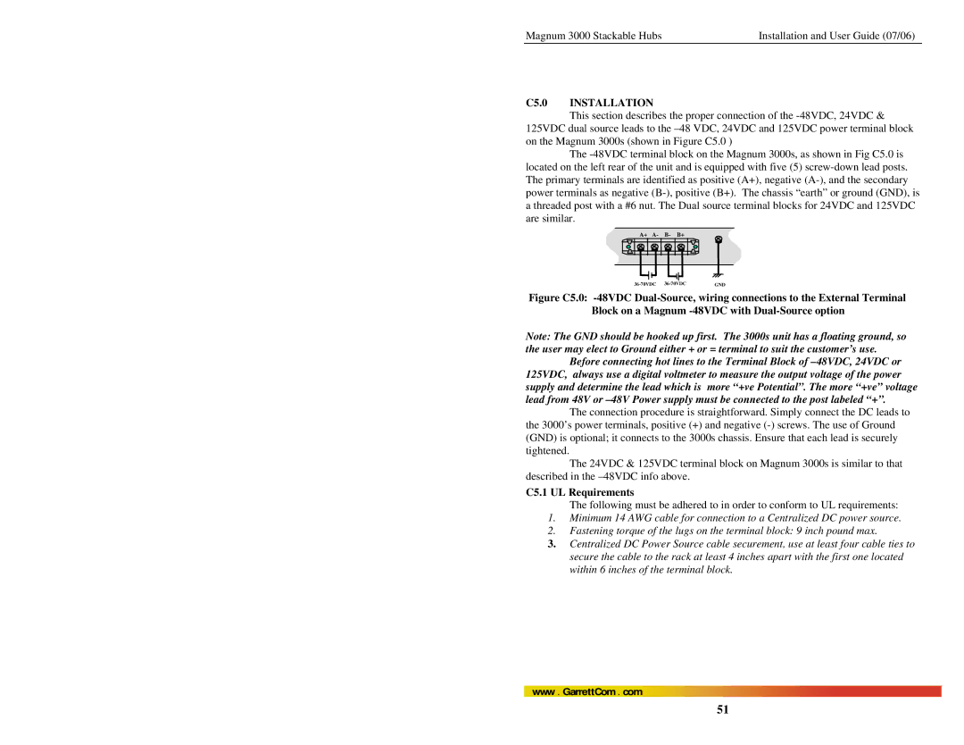
C5.0 Installation
C5.1 UL Requirements
Example Magnum 3024-24VDC or Magnum 3012-125VDC
C6.0 Ordering Information
Example Magnum 3012-48VDC
C7.0 Operation