a45528
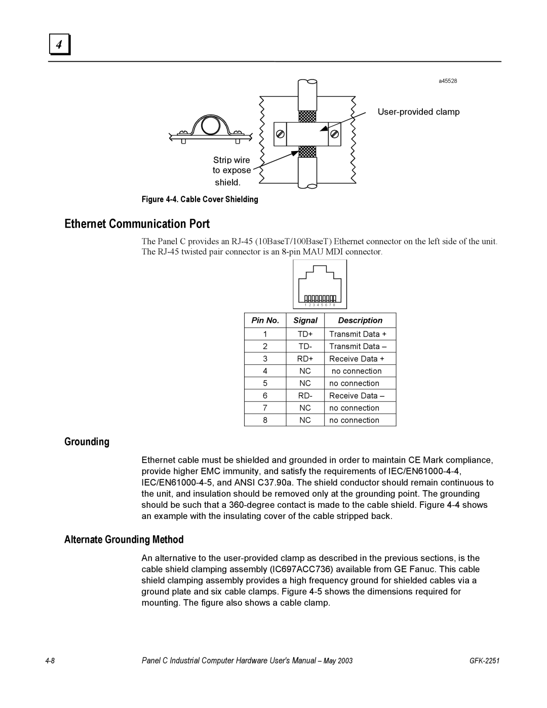
User-provided clamp
Strip wire to expose
shield.
Figure 4-4. Cable Cover Shielding
Ethernet Communication Port
The Panel C provides an RJ-45 (10BaseT/100BaseT) Ethernet connector on the left side of the unit. The RJ-45 twisted pair connector is an 8-pin MAU MDI connector.
| | 1 | 2 | 3 | 4 | 5 | 6 | 7 | 8 | |
| | | | | | | |
| | | | | | |
Pin No. | | Signal | | | | Description |
| | | | | | |
1 | | TD+ | | | | Transmit Data + |
2 | | TD- | | | | | Transmit Data – |
3 | | RD+ | | | | Receive Data + |
4 | | NC | | | | | | no connection |
5 | | NC | | | | | no connection |
6 | | RD- | | | | | Receive Data – |
7 | | NC | | | | | no connection |
8 | | NC | | | | | no connection |
Grounding
Ethernet cable must be shielded and grounded in order to maintain CE Mark compliance, provide higher EMC immunity, and satisfy the requirements of IEC/EN61000-4-4, IEC/EN61000-4-5, and ANSI C37.90a. The shield conductor should remain continuous to the unit, and insulation should be removed only at the grounding point. The grounding should be such that a 360-degree contact is made to the cable shield. Figure 4-4 shows an example with the insulating cover of the cable stripped back.
Alternate Grounding Method
An alternative to the user-provided clamp as described in the previous sections, is the cable shield clamping assembly (IC697ACC736) available from GE Fanuc. This cable shield clamping assembly provides a high frequency ground for shielded cables via a ground plate and six cable clamps. Figure 4-5 shows the dimensions required for mounting. The figure also shows a cable clamp.
4-8 | Panel C Industrial Computer Hardware User's Manual – May 2003 | GFK-2251 |