4 |
2.95" (75 mm)
4.25"
(108 mm)
Mounting
Surface
Side View with
Spacing Requirements
| 19.00" |
|
|
|
|
|
|
| (483 mm) | 18.31" |
|
|
|
| |
|
|
|
|
|
|
| |
.250"(6.35 mm) dia. (QTY.2) |
|
| (465 mm) | ||||
|
|
|
|
|
|
|
|
|
|
|
|
|
|
|
|
|
|
|
|
|
|
|
|
Front View with Mounting Dimensions
Cable Clamp
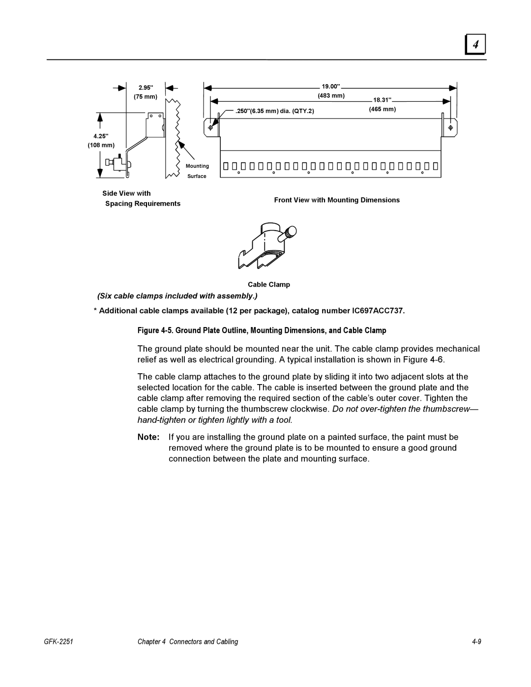
(Six cable clamps included with assembly.)
* Additional cable clamps available (12 per package), catalog number IC697ACC737.
Figure 4-5. Ground Plate Outline, Mounting Dimensions, and Cable Clamp
The ground plate should be mounted near the unit. The cable clamp provides mechanical relief as well as electrical grounding. A typical installation is shown in Figure
The cable clamp attaches to the ground plate by sliding it into two adjacent slots at the selected location for the cable. The cable is inserted between the ground plate and the cable clamp after removing the required section of the cable’s outer cover. Tighten the cable clamp by turning the thumbscrew clockwise. Do not
Note: If you are installing the ground plate on a painted surface, the paint must be removed where the ground plate is to be mounted to ensure a good ground connection between the plate and mounting surface.
| Chapter 4 Connectors and Cabling |
