3 |
Installation Guidelines
AC Input Power
■The Panel C input power shall be connected to no greater than a 20 Amp branch circuit.
■To remove power from the unit, the proper method is to switch off power at the circuit breaker.
Panel Mounting
■In an industrial environment, the panel into which the unit is mounted should provide protection from dust, dirt and water.
■The panel should be capable of supporting the weight (22.2lb/10.07kg) of the industrial computer without distortion to the panel. The mounting clips will support a panel thickness of up to 5mm (0.2 inch).
■All of the mounting clips must be fitted properly to achieve a seal between the industrial computer and the panel to which it is mounted.
■Inlets and outlets must have at least 25mm of space around them and not be obstructed.
Adequate airflow around the exterior of the unit is important to the interior temperature of the unit. Fans are used to create air flow through the industrial computer ensuring that a correct working temperature is maintained. There are three fans in the unit. One of the fans is located on top of the CPU chip and is used to cool the processor. The second fan is built into the power supply housing and blows air out of the unit. The third fan is located on the rear of the chassis cover and pulls air into the unit.
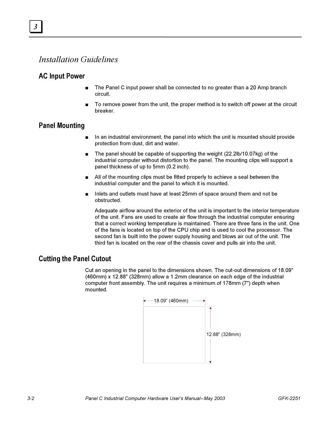
Cutting the Panel Cutout
Cut an opening in the panel to the dimensions shown. The
18.09" (460mm)
12.88" (328mm)
Panel C Industrial Computer Hardware User's |