❑LEVELING THE RANGE
1. Remove the storage drawer, broiler drawer or kick panel.
2.Use a 3/16”
3.Use a 1:%”
4.Install the oven shelves in the oven and position
the range where it will be installed.
5.Check for levelness by placing a spirit level or a cup, partially filled with water, on one of the oven racks. If using a spirit level, take two
6.Adjust the leveling legs until the range is level.
7.After the range is level, slide the range away from the wall so that the
~INSTALLING THE ANT[.T[P DEVICE
W_ING:
Q Range must be secured with an approved
●Unless properly installed, the range could be tipped by you or a child standing, sitting or leaning on an open door.
●After installing the
●This range has been designed to meet all recognized industry tip standards for all normal conditions.
●The use of this device does not preclude tipping of the range when not properly installed.
●If the
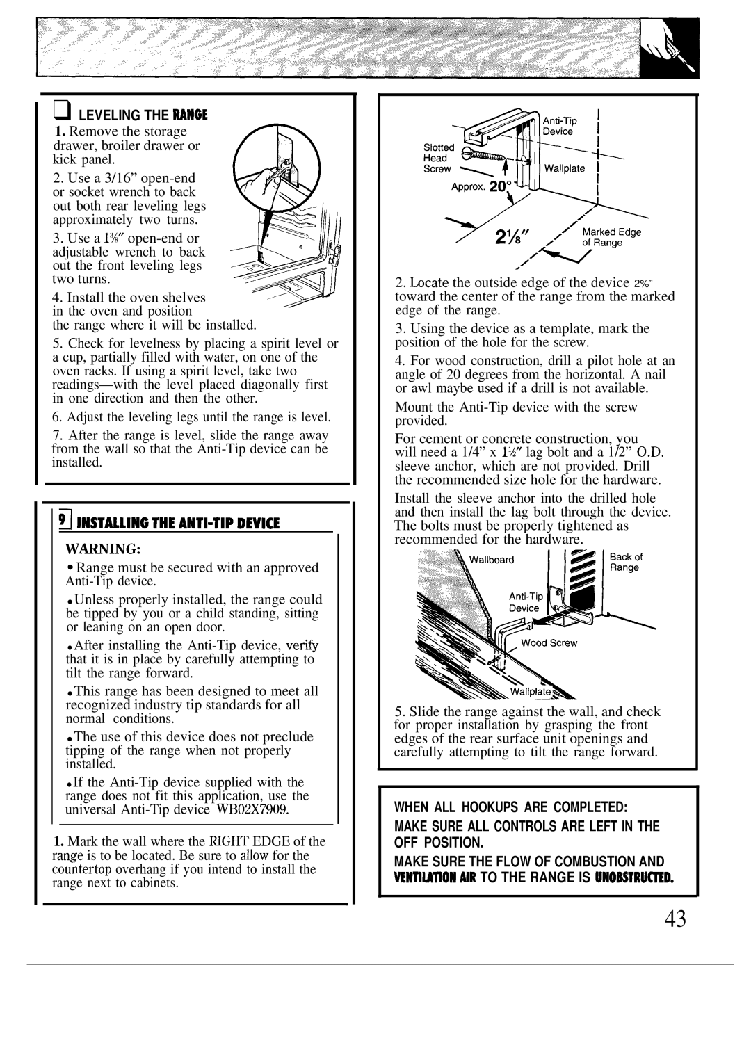
1.Mark the wall where the HGHT EDGE of the range is to be located. Be sure to allow for the cou~tertop overhang if you intend to install the range next to cabinets.
.
2.hcate the outside edge of the device 2%” toward the center of the range from the marked edge of the range.
3.Using the device as a template, mark the position of the hole for the screw.
4.For wood construction, drill a pilot hole at an angle of 20 degrees from the horizontal. A nail or awl maybe used if a drill is not available.
Mount the
For cement or concrete construction, you will need a 1/4” x 1%” lag bolt and a 1/2” O.D. sleeve anchor, which are not provided. Drill the recommended size hole for the hardware.
Install the sleeve anchor into the drilled hole and then install the lag bolt through the device. The bolts must be properly tightened as recommended for the hardware.
5.Slide the range against the wall, and check for proper installation by grasping the front edges of the rear surface unit openings and carefully attempting to tilt the range forward.
WHEN ALL HOOKUPS ARE COMPLETED: MAKE SURE ALL CONTROLS ARE LEFT IN THE OFF POSITION.
MAKE SURE THE FLOW OF COMBUSTION AND VENTIUTION MR TO THE RANGE IS UNOBSTRU~ED.
43