GA-EP45-UD3P
Motherboard
Identifying Your Motherboard Revision
Copyright
Disclaimer
Documentation Classifications
Table of Contents
Drivers Installation
Box Contents
GA-EP45-UD3P Motherboard Layout
Block Diagram
Installation Precautions
Hardware Installation
CPU
Product Specifications
USB
Bios
Installing the CPU
Installing the CPU and CPU Cooler
CPU Socket Lever
Installing the CPU Cooler
Dual Channel Memory Configuration
Installing the Memory
Installing a Memory
Installing an Expansion Card
Installing the Sata Bracket
Back Panel Connectors
Line In Jack Blue
Center/Subwoofer Speaker Out Jack Orange
Rear Speaker Out Jack Black
Side Speaker Out Jack Gray
SATA20/1/2/3/4/5 GSATA20/1
Internal Connectors
ATX12V2X4
F11394
GND
5 CPUFAN/SYSFAN1/SYSFAN2/PWRFAN Fan Headers
FDD Floppy Disk Drive Connector
IDE IDE Connector
Pwrled System Power LED Header
Fpanel Front Panel Header
PW Power Switch, Red
Faudio Front Panel Audio Header
Cdin CD In Connector, Black
Spdifo S/PDIF Out Header
Spdifi S/PDIF In Header, Red
17 F11394 Ieee 1394a Header, Gray
FUSB1/FUSB2 USB Headers, Yellow
Coma Serial Port Header, White
LPT Parallel Port Header
Clrcmos Clearing Cmos Jumper
CI Chassis Intrusion Header
BAT Battery
GA-EP45-UD3P Motherboard
Bios Setup
End Q-FLASH
Logo Screen Default Post Screen
Startup Screen
Function Keys
Main Menu Help
Sample Bios Version E17
Bios Setup Program Function Keys
Main Menu
„ PnP/PCI Configurations
„ Standard Cmos Features
„ Advanced Bios Features
„ Power Management Setup
MB Intelligent TweakerM.I.T
SPD
CPU PLL
CPU Frequency
Robust Graphics Booster
CPU Clock Ratio Note
Fine CPU Clock Ratio Note
Advanced Clok Control
CPU Host Frequency Mhz
PCI Express Frequency Mhz
A.2
MCH Clock Skew
CPU Clock Drive
PCI Express Clock Drive
CPU Clock Skew
TRP
Command RateCMD
CAS Latency Time
TRCD
TRD Phase2 Adjustment
Channel A/B Timing Settings
TRD Phase0 Adjustment
TRD Phase1 Adjustment
Data Driving Pull-Up Level
Channel A/B Driving Settings
DDR Write Training
Driving Strength Profile
CPU Reference
Load-Line Calibration
CPU Vcore
CPU Termination
IDE Channel 0, 1 Master/Slave
Standard Cmos Features
Date
Time
Halt On
Floppy 3 Mode Support
IDE Channel 2, 3 Master, IDE Channel 4, 5 Master/Slave
Drive a
HDD S.M.A.R.T. Capability
Hard Disk Boot Priority
First/Second/Third Boot Device
Password Check
CPU Enhanced Halt C1E Note
CPU Multi-Threading Note
Limit Cpuid Max. to 3 Note
No-Execute Memory Protect Note
Init Display First
Delay For HDD Secs
Dual Bios Recovery Source
Full Screen Logo Show
IDE
Sata RAID/AHCI Mode Intel ICH10R Southbridge
Smart LAN1
Smart LAN2
USB Keyboard Support
Sata Port0-3 Native Mode
USB Controller
USB 2.0 Controller
When a Cable Problem Occurs
Smart LAN1/LAN2 LAN Cable Diagnostic Function
When No LAN Cable Is Attached
When LAN Cable Is Functioning Normally
Onboard SATA/IDE Device Gigabyte SATA2 Chip
Onboard LAN1/LAN2 Boot ROM
Onboard SATA/IDE Ctrl Mode Gigabyte SATA2 Chip
Parallel Port Mode
Power On by Ring
Soft-Off by PWR-BTTN
PME Event Wake Up
Power On By Keyboard
Resume by Alarm
Hpet Mode Note
Power On By Mouse
PnP/PCI Configurations
PCI1 IRQ Assignment
PCI2 IRQ Assignment
CPU Warning Temperature
Reset Case Open Status
Current System/CPU Temperature
Current CPU/SYSTEM/POWER FAN Speed RPM
CPU Smart FAN Control
CPU Smart FAN Mode
Load Optimized Defaults
Load Fail-Safe Defaults
User Password
Supervisor Password
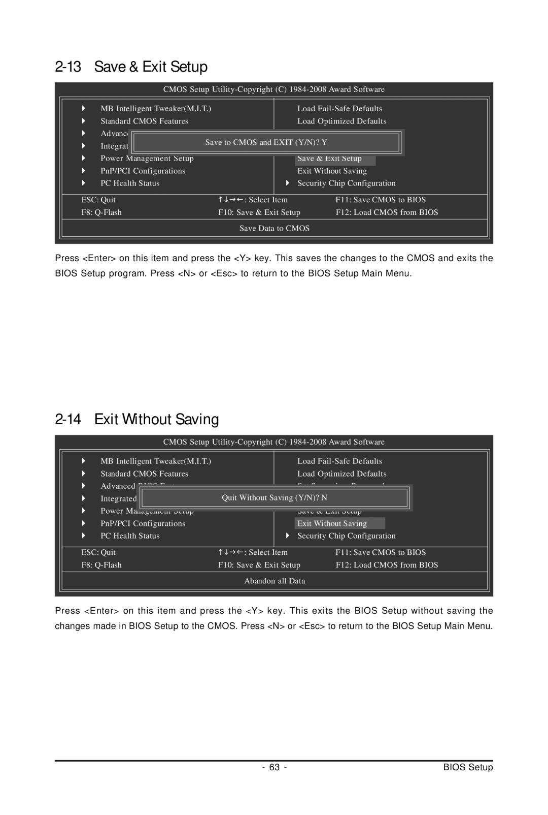
Exit Without Saving
Save & Exit Setup
Security Chip Configuration Note
Security Chip
Security Chip State
Installing Chipset Drivers
Drivers Installation
Technical Manuals
Application Software
System
Contact
Download Center
Xpress Recovery2
Before You Begin
System Requirements
Installing Windows XP and Partitioning the Hard Drive
Installation and Configuration
Page
Using the Backup Function in Xpress Recovery2
Accessing Xpress Recovery2
Using the Restore Function in Xpress Recovery2
Removing the Backup
Exiting Xpress Recovery2
What is Q-FlashTM?
Bios Update Utilities
Updating the Bios with the Q-Flash Utility
What is DualBIOSTM?
Updating the Bios
` Security Chip Configuration
Update the Bios Using the Internet Update Function
Updating the Bios with the @BIOS Utility
Using @BIOS
After Updating the Bios
EasyTune 6 Interface Tabs Information
EasyTune
Dynamic Energy Saver Advanced Interface Meter Mode
Meter Mode Button Information Table
Dynamic Energy Saver Advanced
Total Mode
Total Mode Button Information Table
Stealth Mode
Ultra TPMNote
Instructions for using Ultra TPM
Directions for using Q-Share
Share
Options Descriptions
System Restore
Time Repair
Preference Screen
Removing the Existing Teaming
Realtek Ethernet Diagnostic Utility icon
Teaming
Enabling Teaming Functionality in Windows XP
Enabling Teaming Functionality in Windows Vista
Cation Software, Install Application Software
GA-EP45-UD3P Motherboard
Installing Sata hard drives in your computer
Configuring Sata Hard Drives
Configuring Intel ICH10R Sata Controllers
To configure Sata hard drives, follow the steps below
RAID
Configuring Sata controller mode in Bios Setup
Main Menu
Configuring a RAID array in RAID Bios
Create RAID Volume
DISK/VOLUME Information
Create Volume Menu
ST3120026AS 3JT329JX 111.8GB
Delete Volume Menu
Delete RAID Volume
RAID/IDE
Configuring Gigabyte SATA2 Sata Controller
HDD0
HDD1
ODD0 Dvdrom GO-D1600B
Jbod
Create a RAID Array
Steps
Graid
Model Name Available Type/Status Level Stripe
RDD0 Graid
` RDD0 Graid
Delete the RAID Array
Making a Sata RAID/AHCI Driver Diskette
Required for Ahci and RAID Mode
Page
Installing Windows XP
Installing the Sata RAID/AHCI Driver and Operating System
GA-EP45-UD3P Motherboard 102
103 Appendix
GA-EP45-UD3P Motherboard 104
Intel ICH10R Sata controllers
Installing Windows Vista
Page
Gigabyte SATA2 controllers
Page
High Definition Audio HD Audio
Configuring Audio Input and Output
Configuring 2/4/5.1/7.1-Channel Audio
Configuring Speakers
Configuring Sound Effect
Activating an AC97 Front Panel Audio Module
Muting the Back Panel Audio For HD Audio Only
Installing the S/PDIF In Cable Optional
Installing the S/PDIF In Cable
Pdif
Configuring S/PDIF out
Pdif Out
Conneting a S/PDIF out Cable
Click Dolby Pro Logic
Enabling the Dolby Home Theater Function
Windows XP
Windows Vista
Configuring Microphone Recording
115 Appendix
Using the Sound Recorder
Recording the Sound
Playing the Sound
Frequently Asked Questions
Troubleshooting
Start
Troubleshooting Procedure
END
Our Commitment to Preserving the Environment
Weee Symbol Statement
Regulatory Statements
Regulatory Notices
China Restriction of Hazardous Substances Table
GA-EP45-UD3P Motherboard 122
123 Appendix
GA-EP45-UD3P Motherboard 124
125 Appendix
GA-EP45-UD3P Motherboard 126
B.T. INC USA Mexico
Contact Us
Gigabyte Global Service System