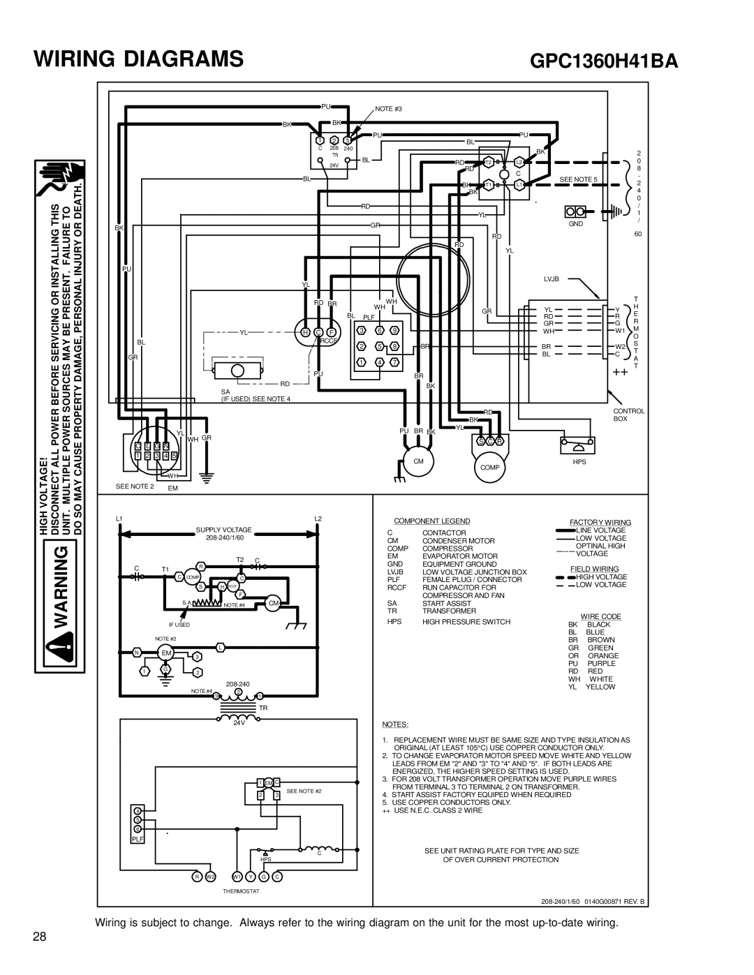
WIRING DIAGRAMS

GPC1360H41BA

VOLTAGE! DISCONNECT ALL POWER BEFORE SERVICING OR INSTALLING THIS MULTIPLE POWER SOURCES MAY BE PRESENT. FAILURE TO SO MAY CAUSE PROPERTY DAMAGE, PERSONAL INJURY OR DEATH.


PU


NOTE #3


BK


BK


1

2

3

PU


BL


PU


C

208

240


BK


24V

BL


RD

T2

L2


RD


C


BL


BK


SEE NOTE 5


T1

L1


BK


RD


YL


BK


GR


GND


RD

RD


YL


PU


YL


LVJB


RD BR


WH

WH


GR

YL


BL PLF


RD


3

6

9


GR


YL

H C

F


WH

BL


RCCF

2

5

8

BR


BR


GR


1

4

7


BL


RD

PU


BR


BK


SA


(IF USED) SEE NOTE 4


BK

RD


YL


PU

BR

BK

YL


C


WH GR


S C R


L G N


1

2

3

4

5


CM


HPS


COMP


WH


SEE NOTE 2


EM


2

0

8

-

2

4

0

/

1

/

60

T

YH

R E

G R W1 M O

W2 S

C T

A

++T

CONTROL BOX

HIGH WARNING UNIT. DO

L1


L2


SUPPLY VOLTAGE


208-240/1/60


C


R

T2

C


T1


C COMP


C


S

H RCCF


F


S.A.

NOTE #4


CM


IF USED


NOTE #2


N

EM


L


3


1

G

2


NOTE #4

208-240


2

1


3


TR


24V


1 EM C


2

3

SEE NOTE #2


4

5

6

PLF

C

HPS

R W2 W1 Y G C

THERMOSTAT

COMPONENT LEGEND


FACTORY WIRING

C

CONTACTOR


LINE VOLTAGE

CM

CONDENSER MOTOR


LOW VOLTAGE


COMP

COMPRESSOR


OPTINAL HIGH


VOLTAGE

EM

EVAPORATOR MOTOR


GND

EQUIPMENT GROUND


FIELD WIRING

LVJB

LOW VOLTAGE JUNCTION BOX


HIGH VOLTAGE

PLF

FEMALE PLUG / CONNECTOR


LOW VOLTAGE

RCCF

RUN CAPACITOR FOR


SA

COMPRESSOR AND FAN


START ASSIST


TR

TRANSFORMER


WIRE CODE

HPS

HIGH PRESSURE SWITCH


BK

BLACK


BL

BLUE


BR

BROWN


GR

GREEN


OR

ORANGE


PU

PURPLE


RD

RED


WH

WHITE


YL

YELLOW

NOTES:

1.REPLACEMENT WIRE MUST BE SAME SIZE AND TYPE INSULATION AS ORIGINAL (AT LEAST 105°C) USE COPPER CONDUCTOR ONLY.

2.TO CHANGE EVAPORATOR MOTOR SPEED MOVE WHITE AND YELLOW LEADS FROM EM "2" AND "3" TO "4" AND "5". IF BOTH LEADS ARE ENERGIZED, THE HIGHER SPEED SETTING IS USED.

3.FOR 208 VOLT TRANSFORMER OPERATION MOVE PURPLE WIRES FROM TERMINAL 3 TO TERMINAL 2 ON TRANSFORMER.

4.START ASSIST FACTORY EQUIPED WHEN REQUIRED

5.USE COPPER CONDUCTORS ONLY.

++ USE N.E.C. CLASS 2 WIRE

SEE UNIT RATING PLATE FOR TYPE AND SIZE

OF OVER CURRENT PROTECTION

208-240/1/60 0140G00871 REV. B

Wiring is subject to change. Always refer to the wiring diagram on the unit for the most up-to-date wiring.

28

Page 28
Image 28
Goodmans GPC 13 SEER R-410A, GPC1324H41A service manual GPC1360H41BA

GPC1324H41A, GPC 13 SEER R-410A specifications

The Goodman GPC 13 SEER R-410A, model GPC1324H41A, represents a reliable and efficient option for those seeking a powerful packaged air conditioning system. This unit is designed to provide cooling for both residential and light commercial applications, offering a blend of performance, durability, and affordability.

One of the standout features of the Goodman GPC 13 is its cooling efficiency rating of 13 SEER (Seasonal Energy Efficiency Ratio). This efficiency rating not only underscores its capability to provide effective cooling but also ensures that consumers can enjoy lower utility bills compared to older, less efficient systems. The use of R-410A refrigerant is another significant characteristic of this model, as R-410A is known for its enhanced performance and environmentally friendly properties, being free from hydrochlorofluorocarbons (HCFCs) that can deplete the ozone layer.

The GPC1324H41A is equipped with a high-quality scroll compressor which contributes to its quiet operation and improved reliability. Scroll compressors have fewer moving parts than traditional compressors, which translates to reduced wear and tear, ensuring a longer lifespan for the unit. Additionally, this model includes an efficient evaporator coil that maximizes heat exchange, further enhancing the overall cooling performance.

Another notable characteristic of the Goodman GPC 13 is its design for easy installation and maintenance. The unit features a compact, all-in-one design that simplifies the installation process, making it suitable for various settings without requiring extensive modifications. Moreover, the GPC1324H41A features easily accessible components, which facilitates routine maintenance and servicing, ultimately leading to improved system longevity.

The robust construction of the weather-resistant cabinet ensures that the unit can withstand various environmental conditions, making it an ideal choice for outdoor installations. The durable finish not only adds to the unit’s aesthetics but also helps protect it from rust and corrosion, ensuring a reliable performance over the years.

In summary, the Goodman GPC 13 SEER R-410A, model GPC1324H41A, combines efficiency, durability, and ease of use. With its reliable features, advanced technologies, and environmentally conscious design, this packaged air conditioning system stands out as a solid investment for homeowners and businesses looking to enhance their indoor comfort.