Setting Spindle
Speed
To select the correct spindle speed (RPM) for your milling operation, you will need to: 1) Determine the spindle speed needed for your workpiece, and 2) set the speed dial for the calculated speed.
This mill is designed to use most end mills, drill bits, and face cutters that are 3" in diameter or less. The milling table has a coolant system trough with drain for an optional fluid system.
Calculating Spindle Speed
1.Use the table in Figure 29 to determine the cutting speed or surface feet per minute (SFM) required for your workpiece material.
Cutting Speeds for High Speed Steel (HSS)
Cutting Tools
Workpiece Material | Cutting Speed (SFM) |
Aluminum & alloys | 300 |
|
|
Brass & Bronze | 150 |
|
|
Copper | 100 |
|
|
Cast Iron, soft | 80 |
|
|
Cast Iron, hard | 50 |
|
|
Mild Steel | 90 |
|
|
Cast Steel | 80 |
|
|
Alloy Steel, hard | 40 |
|
|
Tool Steel | 50 |
|
|
Stainless Steel | 60 |
|
|
Titanium | 50 |
|
|
Plastics | |
|
|
Wood | |
|
|
Note: For carbide cutting tools, double the cutting speed. These values are a guideline only. Refer to the MACHINERY'S HANDBOOK for more detailed information.
Figure 29. Cutting speed table for HSS cutting
tools.
2.Measure the diameter of your cutting tool in decimal inches.
3.Use the following formula to calculate the required spindle speed (RPM) for your opera- tion:
Setting Spindle Speed
1.Rotate the speed dial all the way to the left, setting the startup spindle speed close to zero.
Note: This precaution avoids unexpected high speed startup of the spindle.
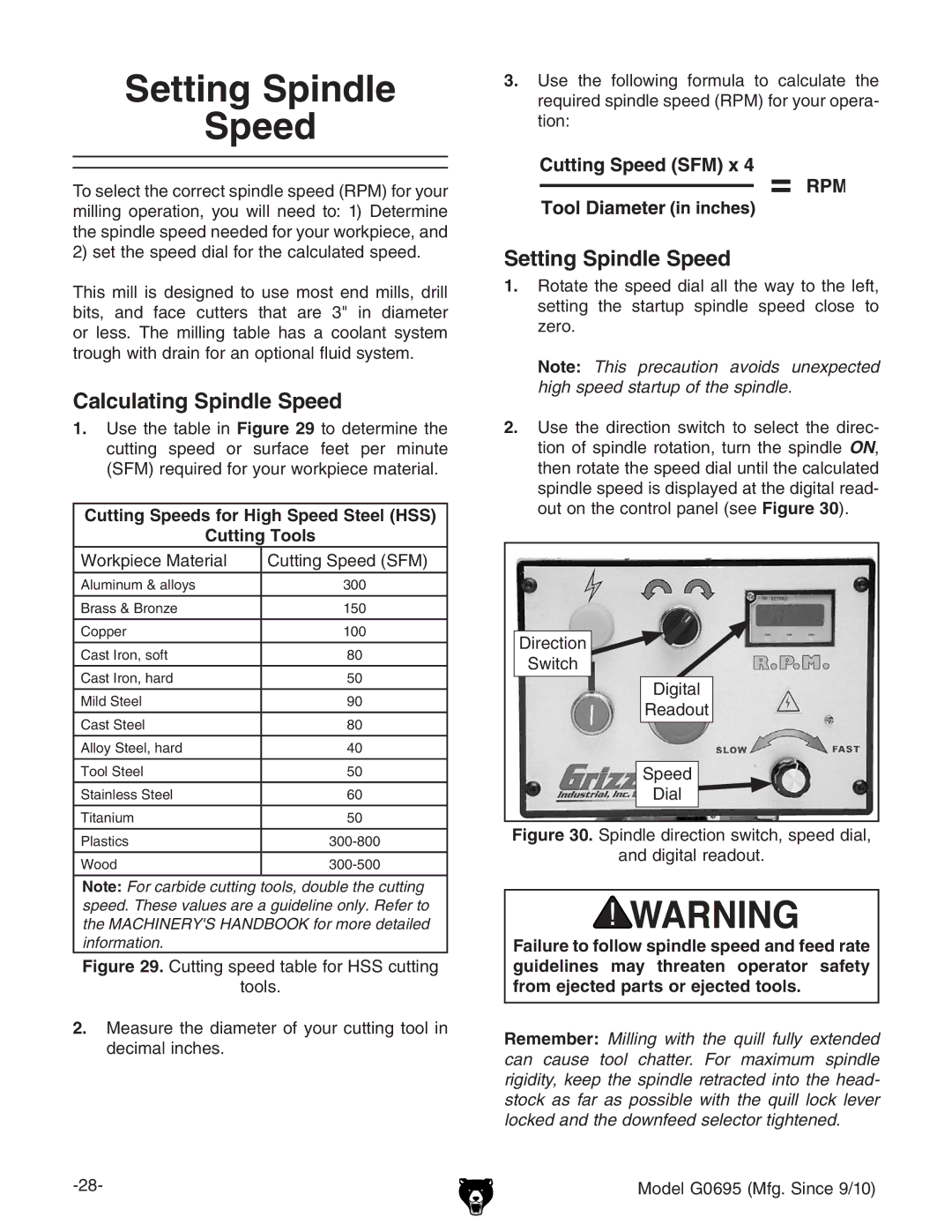
2.Use the direction switch to select the direc- tion of spindle rotation, turn the spindle ON, then rotate the speed dial until the calculated spindle speed is displayed at the digital read- out on the control panel (see Figure 30).
Direction
Switch
Digital
Readout
Speed
Dial
Figure 30. Spindle direction switch, speed dial,
and digital readout.
Failure to follow spindle speed and feed rate guidelines may threaten operator safety from ejected parts or ejected tools.
Remember: Milling with the quill fully extended can cause tool chatter. For maximum spindle rigidity, keep the spindle retracted into the head- stock as far as possible with the quill lock lever locked and the downfeed selector tightened.
Model G0695 (Mfg. Since 9/10)