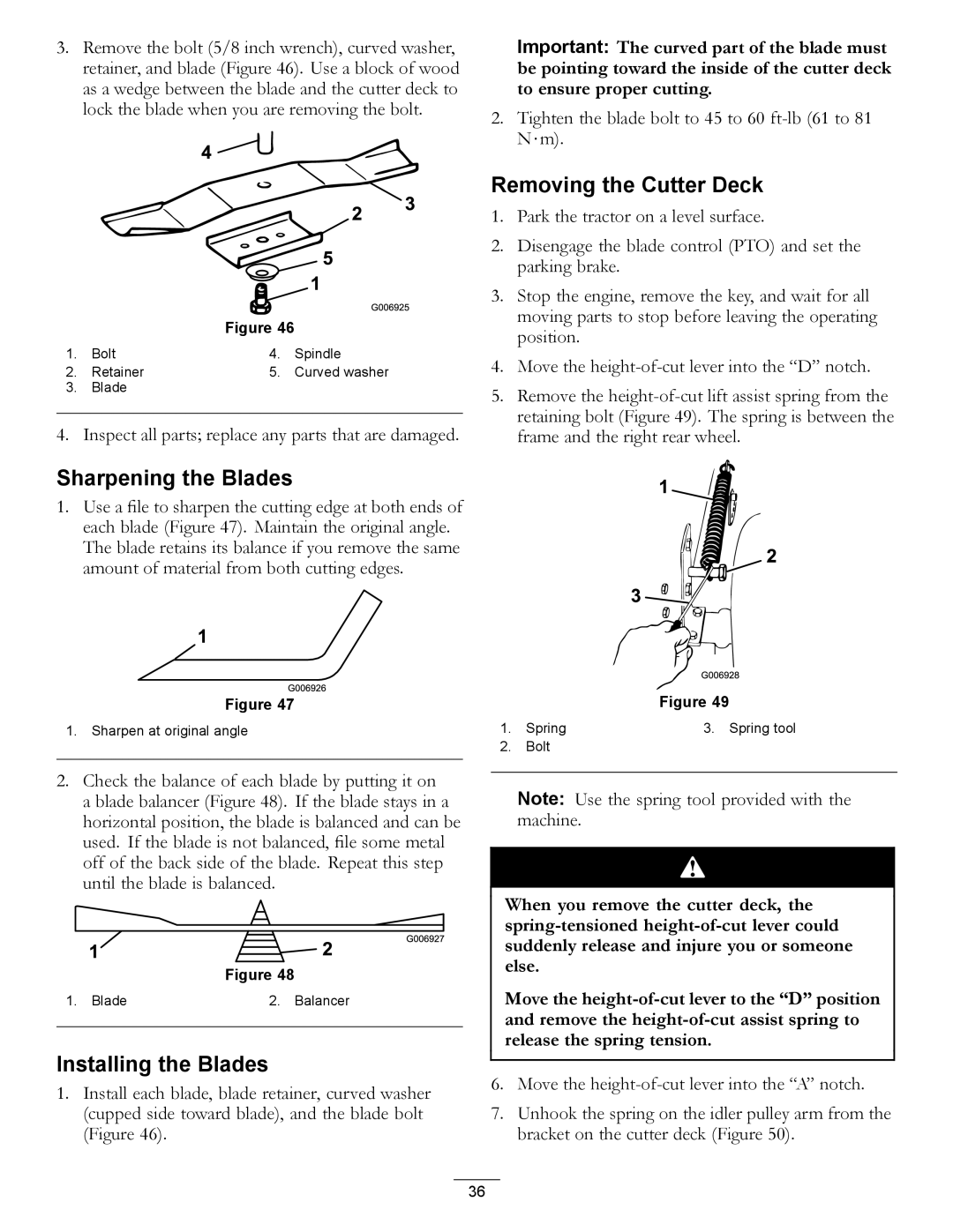
3.Remove the bolt (5/8 inch wrench), curved washer, retainer, and blade (Figure 46). Use a block of wood as a wedge between the blade and the cutter deck to lock the blade when you are removing the bolt.
Figure 46
1. | Bolt | 4. | Spindle |
2. | Retainer | 5. | Curved washer |
3.Blade
4.Inspect all parts; replace any parts that are damaged.
Important: The curved part of the blade must be pointing toward the inside of the cutter deck to ensure proper cutting.
2.Tighten the blade bolt to 45 to 60
Removing the Cutter Deck
1.Park the tractor on a level surface.
2.Disengage the blade control (PTO) and set the parking brake.
3.Stop the engine, remove the key, and wait for all moving parts to stop before leaving the operating position.
4.Move the
5.Remove the
Sharpening the Blades
1.Use a file to sharpen the cutting edge at both ends of each blade (Figure 47). Maintain the original angle. The blade retains its balance if you remove the same amount of material from both cutting edges.
Figure 47
1.Sharpen at original angle
2.Check the balance of each blade by putting it on a blade balancer (Figure 48). If the blade stays in a horizontal position, the blade is balanced and can be used. If the blade is not balanced, file some metal off of the back side of the blade. Repeat this step until the blade is balanced.
Figure 48
1. Blade | 2. Balancer |
|
|
Installing the Blades
1.Install each blade, blade retainer, curved washer (cupped side toward blade), and the blade bolt (Figure 46).
|
| Figure 49 |
1. | Spring | 3. Spring tool |
2. | Bolt |
|
Note: Use the spring tool provided with the machine.
When you remove the cutter deck, the
Move the
6.Move the
7.Unhook the spring on the idler pulley arm from the bracket on the cutter deck (Figure 50).
36