Step 3
Installing the
Vent System
A. Vent System Approvals
This model is approved to use
TEMS OR COMPONENTS MAY BE USED.
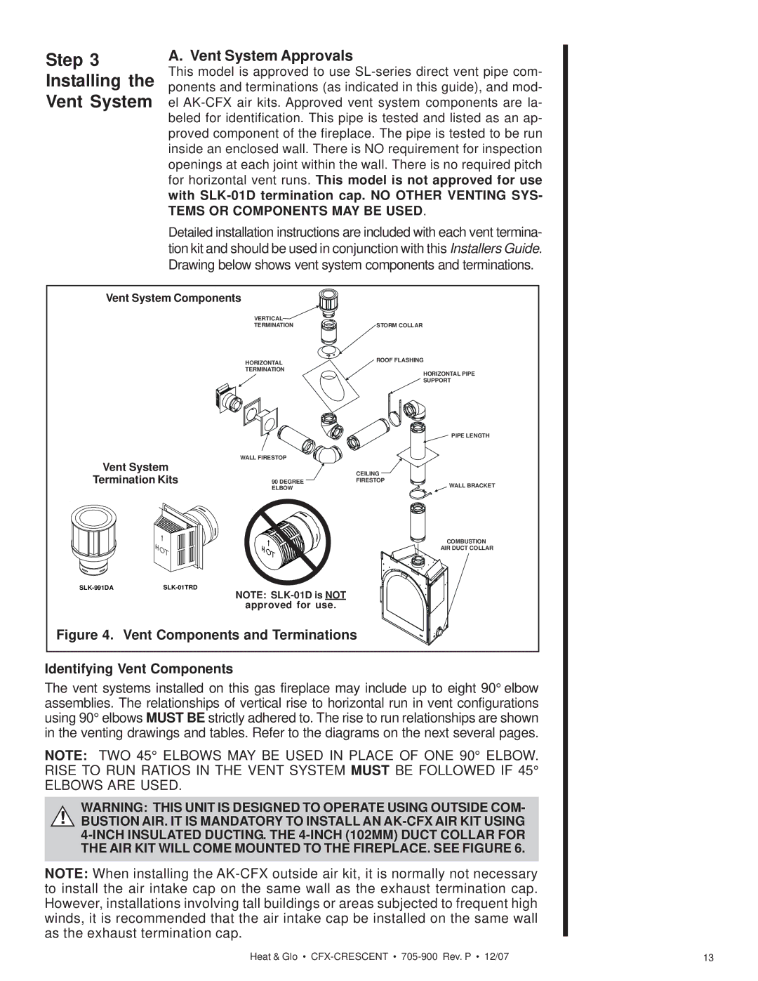
Detailed installation instructions are included with each vent termina- tion kit and should be used in conjunction with this Installers Guide. Drawing below shows vent system components and terminations.
Vent System Components |
| ||
|
| VERTICAL |
|
|
| TERMINATION | STORM COLLAR |
|
| HORIZONTAL | ROOF FLASHING |
|
| TERMINATION | HORIZONTAL PIPE |
|
|
| |
|
|
| SUPPORT |
|
|
| PIPE LENGTH |
Vent System | WALL FIRESTOP |
| |
| CEILING | ||
Termination Kits |
| ||
90 DEGREE | FIRESTOP | ||
|
| ELBOW | WALL BRACKET |
|
|
| |
|
|
| COMBUSTION |
|
|
| AIR DUCT COLLAR |
NOTE: |
| ||
|
|
| |
|
| approved for use. |
|
Figure 4. Vent Components and Terminations | |||
Identifying Vent Components
The vent systems installed on this gas fireplace may include up to eight 90° elbow assemblies. The relationships of vertical rise to horizontal run in vent configurations using 90° elbows MUST BE strictly adhered to. The rise to run relationships are shown in the venting drawings and tables. Refer to the diagrams on the next several pages.
NOTE: TWO 45° ELBOWS MAY BE USED IN PLACE OF ONE 90° ELBOW. RISE TO RUN RATIOS IN THE VENT SYSTEM MUST BE FOLLOWED IF 45° ELBOWS ARE USED.
WARNING: THIS UNIT IS DESIGNED TO OPERATE USING OUTSIDE COM-
!BUSTION AIR. IT IS MANDATORY TO INSTALL AN
NOTE: When installing the
Heat & Glo • | 13 |
