6 Termination Locations
A. Vent Termination Minimum Clearances
![]() WARNING
WARNING
Fire Risk.
Maintain vent clearance to combustibles as specified.
• DO NOT pack air space with insulation or other materials.
Failure to keep insulation or other materials away from vent pipe may cause overheating and fire.
HORIZONTAL
OVERHANG
510 mm MIN.
610 mm MIN.
VERTICAL
WALL
LOWEST
DISCHARGE
OPENING
TERMINATION
CAP
X
305 mm
![]() ROOF PITCH
ROOF PITCH
IS X/ 305 mm
H (MIN.) - MINIMUM HEIGHT FROM ROOF
TO LOWEST DISCHARGE OPENING
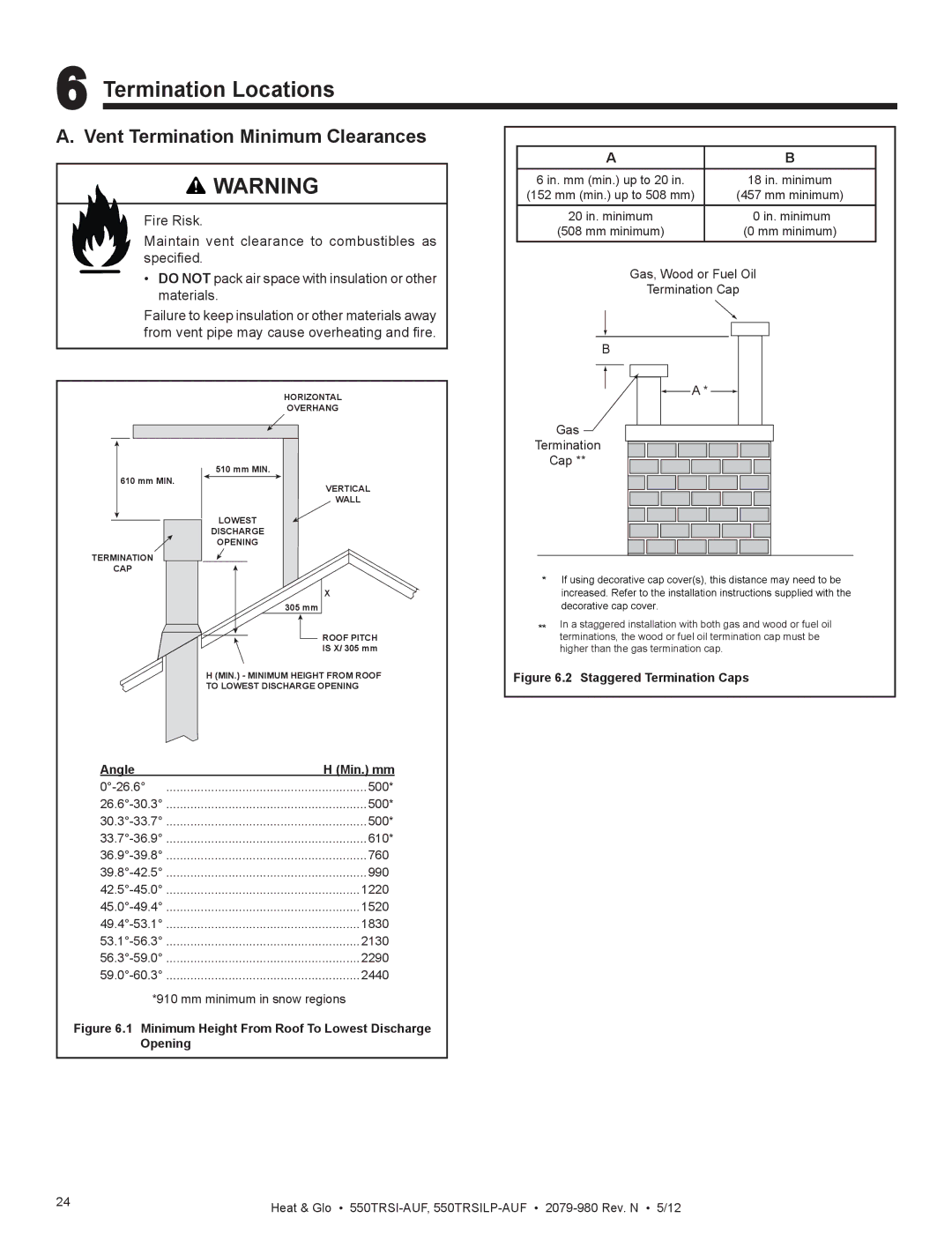
Angle | H (Min.) mm |
500* | |
500* | |
500* | |
610* | |
760 | |
990 | |
1220. | |
1520. | |
1830. | |
2130. | |
2290. | |
2440. |
*910 mm minimum in snow regions
Figure 6.1 Minimum Height From Roof To Lowest Discharge Opening
A | B |
6 in. mm (min.) up to 20 in. | 18 in. minimum |
(152 mm (min.) up to 508 mm) | (457 mm minimum) |
20 in. minimum | 0 in. minimum |
(508 mm minimum) | (0 mm minimum) |
Gas, Wood or Fuel Oil
Termination Cap
B
![]() A *
A * ![]()
Gas
Termination
Cap **
*If using decorative cap cover(s), this distance may need to be increased. Refer to the installation instructions supplied with the decorative cap cover.
**In a staggered installation with both gas and wood or fuel oil terminations, the wood or fuel oil termination cap must be higher than the gas termination cap.
Figure 6.2 Staggered Termination Caps
24 | Heat & Glo • |
|