8 Vent Clearances and Framing
A. Pipe Clearances to Combustibles | B. Wall Penetration Framing |
|
| |||||||
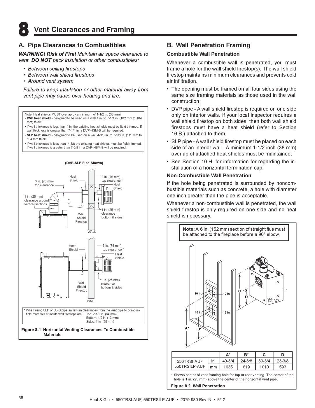
WARNING! Risk of Fire! Maintain air space clearance to | Combustible Wall Penetration |
|
| |||||||
vent. DO NOT pack insulation or other combustibles: | Whenever a combustible wall is penetrated, you must | |||||||||
|
|
|
| |||||||
• | Between ceiling firestops |
| frame a hole for the wall shield firestop(s). The wall shield | |||||||
• | Between wall shield firestops | firestop maintains minimum clearances and prevents cold | ||||||||
• Around vent system |
| air infiltration. |
|
|
|
|
| |||
Failure to keep insulation or other material away from | • The opening must be framed on all four sides using the | |||||||||
vent pipe may cause over heating and fire. | same size framing materials as those used in the wall | |||||||||
|
|
|
| construction. |
|
|
|
|
| |
|
|
|
| • DVP pipe - A wall shield firestop is required on one side | ||||||
Note: Heat shields MUST overlap by a minimum of | only on interior walls. If your local inspector requires a | |||||||||
• DVP heat shield - designed to be used on a wall 4 in. to | wall shield firestop on both sides, then both wall shield | |||||||||
| mm) thick. |
|
| |||||||
• If wall thickness is less than 4 in. the existing heat shields must be field trimmed. If | firestops | must | have | a heat | shield | (refer | to Section | |||
| wall thickness is greater than | 16.B.) attached to them. |
|
|
| |||||
• SLP heat shield - designed to be used on a wall |
|
|
| |||||||
| 194 mm thick). |
|
| • SLP pipe - A wall shield firestop must be placed on each | ||||||
• If wall thickness is less than | ||||||||||
| If wall thickness is greater than | side of an interior wall. A minimum | ||||||||
|
|
|
| overlap of attached heat shields must be maintained. | ||||||
|
| • See Section 10.H. for information for regarding the in- | ||||||||
|
|
|
| stallation of a horizontal termination cap. |
| |||||
|
| Heat | 3 in. (76 mm) |
|
|
| ||||
| 3 in. (76 mm) | Shield | top clearance * | If the hole being penetrated is surrounded by noncom- | ||||||
| top clearance |
| Heat | |||||||
|
|
| Shield | bustible materials such as concrete, a hole with diameter | ||||||
|
|
|
|
|
|
|
|
|
| |
1 in. (25 mm) |
|
| one inch greater than the pipe is acceptable. |
| ||||||
clearance around |
|
| Whenever a | |||||||
vertical sections |
|
| ||||||||
|
|
| 1 in. (25 mm) | shield firestop is only required on one side and no heat | ||||||
|
| Wall | clearance | shield is necessary. |
|
|
|
| ||
|
| Shield | bottom & sides |
|
|
|
| |||
|
| Firestop |
|
|
|
|
|
|
| |
|
|
| WALL | Note: A 6 in. (152 mm) section of straight flue must | ||||||
|
|
| be attached to the fireplace before a 90° elbow. | |||||||
|
|
|
| |||||||
|
| Heat | 3 in. (76 mm) |
|
|
|
|
|
|
|
|
| Shield | top clearance * |
|
|
|
|
|
|
|
|
|
| Heat |
|
|
|
|
|
|
|
|
|
| Shield |
|
|
|
|
|
|
|
|
| Wall | 1 in. (25 mm) |
|
|
|
|
|
|
|
|
| clearance |
|
|
|
|
|
|
| |
|
| Shield | bottom & sides |
|
|
|
| C |
|
|
|
| Firestop |
| 10 in. |
| 10 in. |
|
| ||
|
|
|
|
|
| D |
|
| ||
|
|
| WALL |
|
|
|
|
|
| |
|
|
|
|
|
|
|
|
|
| |
* When using SLP or |
| 10 in. |
| 12 in. |
|
|
| |||
| tible materials at inside wall firestops are: Top: |
|
|
|
|
| ||||
|
|
|
|
|
|
|
| |||
|
|
| Bottom: 1/2 in. (13 mm) |
|
|
|
|
|
|
|
|
|
| Sides: 1 in. (25 mm) |
|
|
|
|
|
|
|
Figure 8.1 Horizontal Venting Clearances To Combustible | A* | B* |
|
|
|
|
| |||
| Materials |
|
|
|
|
|
|
|
|
|
|
|
|
|
|
|
| A* | B* | C | D |
|
|
|
| in. | ||||||
|
|
|
|
| mm | 1035 | 619 | 1010 | 593 | |
|
|
|
| * Shows center of vent framing hole for top or rear venting. The center of the | ||||||
|
|
|
| hole is 1 in. (25 mm) above the center of the horizontal vent pipe. | ||||||
|
|
|
| Figure 8.2 | Wall Penetration |
|
|
| ||
38 |
|
| Heat & Glo • |
|
|
| ||||
|
|
|
|
|
| |||||