Heat & Glo LifeStyle 550TRSI-AUF C. Vent Components Diagrams continued, DVP-TRAP2, 15-1/8in

Models: 550TRSI-AUF

1 80
Download 80 pages 27.78 Kb
Page 73
Image 73
C. Vent Components Diagrams (continued)

C. Vent Components Diagrams (continued)

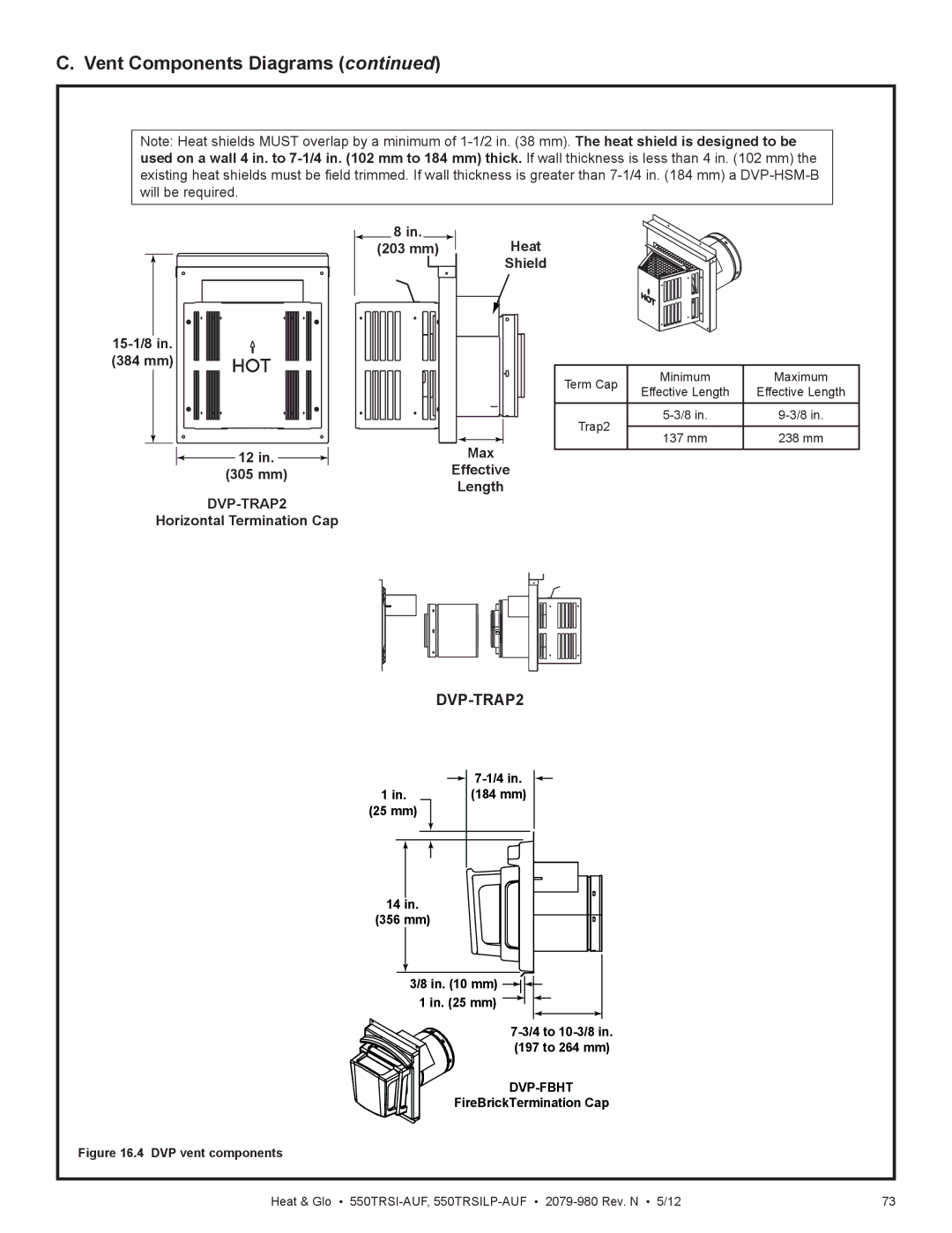
Note: Heat shields MUST overlap by a minimum of 1-1/2 in. (38 mm). The heat shield is designed to be used on a wall 4 in. to 7-1/4 in. (102 mm to 184 mm) thick. If wall thickness is less than 4 in. (102 mm) the existing heat shields must be field trimmed. If wall thickness is greater than 7-1/4 in. (184 mm) a DVP-HSM-B will be required.

8 in.

(203 mm) Heat Shield

15-1/8 in.


(384 mm)


Minimum

Maximum


Term Cap


Effective Length

Effective Length


Trap2

5-3/8 in.

9-3/8 in.


137 mm

238 mm


Max

12 in.


(305 mm)

Effective


Length


DVP-TRAP2

Horizontal Termination Cap

DVP-TRAP2

7-1/4 in.

1 in. (184 mm)

(25 mm)

14in.

(356 mm)

3/8 in. (10 mm) 8 in.15-1/8 in.(384 mm) 1 in. (25 mm) 12 in.Effective

7-3/4 to 10-3/8 in.

(197 to 264 mm)

DVP-FBHT

FireBrickTermination Cap

Figure 16.4 DVP vent components

Heat & Glo • 550TRSI-AUF, 550TRSILP-AUF2079-980 Rev. N • 5/12

73

Page 73
Image 73
Heat & Glo LifeStyle 550TRSI-AUF C. Vent Components Diagrams continued, DVP-TRAP2, 8 in 203 mm Heat Shield, 15-1/8in