V
X
D
E
v
L
v B | C |
|
v
![]() F
F![]() v
v
B
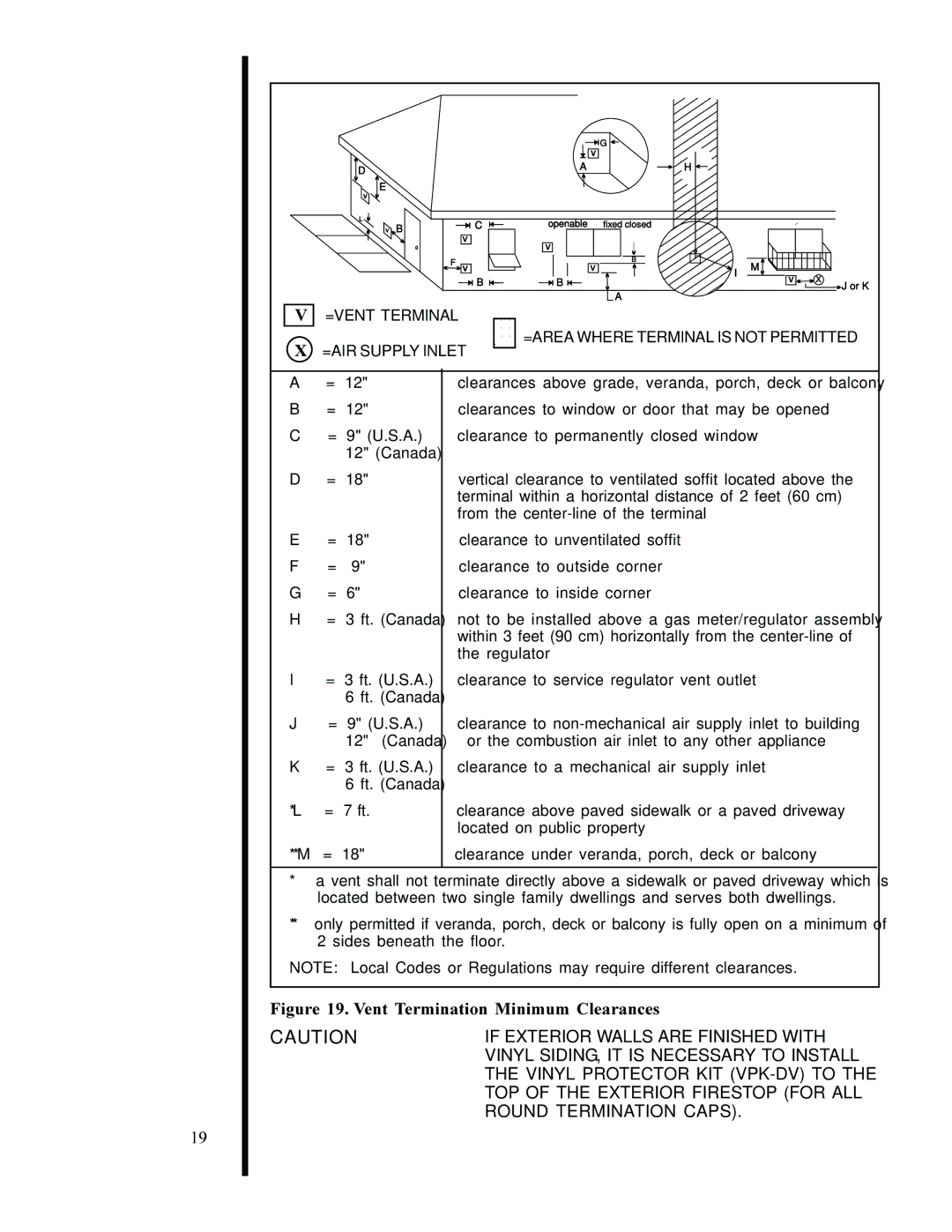
=VENT TERMINAL
=AIR SUPPLY INLET
2
![]()
![]() G
G ![]()
![]() v
v
A | H |
|
| |
openable | fixed closed |
|
| |
v |
|
|
| |
v | B | M |
| |
I |
| |||
B | v | X | ||
| ||||
|
| J or K | ||
| A |
| ||
|
|
|
=AREA WHERE TERMINAL IS NOT PERMITTED
A= 12" B = 12"
C= 9" (U.S.A.) 12" (Canada)
D= 18"
E= 18"
F= 9" G = 6"
H = 3 ft. (Canada)
I= 3 ft. (U.S.A.) 6 ft. (Canada)
J= 9" (U.S.A.) 12" (Canada)
K= 3 ft. (U.S.A.) 6 ft. (Canada)
*L = 7 ft.
**M = 18"
clearances above grade, veranda, porch, deck or balcony clearances to window or door that may be opened clearance to permanently closed window
vertical clearance to ventilated soffit located above the terminal within a horizontal distance of 2 feet (60 cm) from the
clearance to unventilated soffit clearance to outside corner clearance to inside corner
not to be installed above a gas meter/regulator assembly within 3 feet (90 cm) horizontally from the
clearance to service regulator vent outlet
clearance to
clearance to a mechanical air supply inlet
clearance above paved sidewalk or a paved driveway located on public property
clearance under veranda, porch, deck or balcony
19
*a vent shall not terminate directly above a sidewalk or paved driveway which is located between two single family dwellings and serves both dwellings.
**only permitted if veranda, porch, deck or balcony is fully open on a minimum of 2 sides beneath the floor.
NOTE: Local Codes or Regulations may require different clearances.
Figure 19. Vent Termination Minimum Clearances
CAUTION | IF EXTERIOR WALLS ARE FINISHED WITH |
| VINYL SIDING, IT IS NECESSARY TO INSTALL |
| THE VINYL PROTECTOR KIT |
| TOP OF THE EXTERIOR FIRESTOP (FOR ALL |
| ROUND TERMINATION CAPS). |