Step 8
Wiring the
Fireplace
CAUTION
NOTE: Electrical wiring must be installed by a licensed electrician.
Caution: Disconnect remote controls if you are absent for extended time periods. This will prevent accidental fireplace operation.
For Standing Pilot Ignition Wiring
Appliance Requirements
•This appliance DOES NOT require 110-120 VAC to operate.
WARNING
DO NOT CONNECT
Optional Accessories
Optional fan and remote control kits require that 110- 120 VAC be wired to the factory installed junction box before the fireplace is permanently installed.
Remote Wall Switch
Position the remote wall switch in the desired position on a wall. Run a maximum of 25 feet (7.8 m) or less length of 18 A.W.G. minimum wire and connect it to the fireplace ON/OFF switch pigtails.
WARNING
DO NOT CONNECT
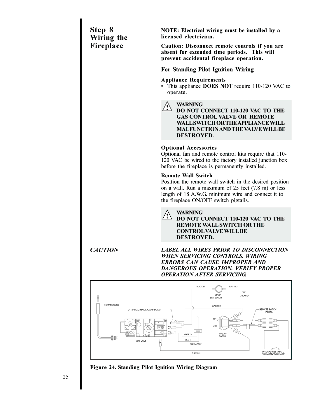
LABEL ALL WIRES PRIOR TO DISCONNECTION WHEN SERVICING CONTROLS. WIRING ERRORS CAN CAUSE IMPROPER AND DANGEROUS OPERATION. VERIFY PROPER OPERATION AFTER SERVICING.
25